Field installation
The instrument is typically installed on a tripod or tower for eddy covariance applications. This section describes how to install the instrument and its associated components.
Mounting the gas analyzer and sonic anemometer
The LI-7200RS sensor is installed or a tripod or tower with a combination of the mounting post and the mounting kit (part number 7900-340). Set screws should be tightened to 22 N•m (16 ft•lbs). If no torque wrench is available, tighten each set screw until it contacts the pipe, then one more full revolution for aluminum pipe, or ¼ revolution for stainless steel. Use a 5/32" hex key for all the fittings except the ¾" × 1" crossover fitting (7900-342), which uses a 3/16" hex key.
Site considerations
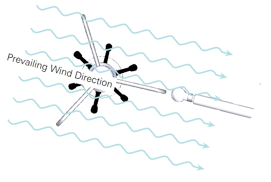
Plan your site with respect to the geographical area that is contributing to fluxes. Position the system downwind from that area. For mast-style anemometers, position the gas analyzer inlet adjacent to a spar on the downwind side of the anemometer.
Installing the head mounting post
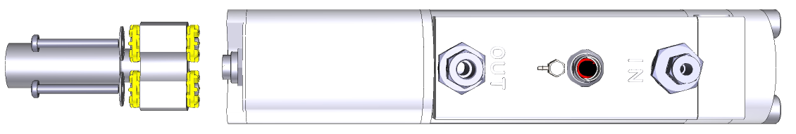
Begin by attaching the head mounting post to the analyzer head.
Mounting the sensor head
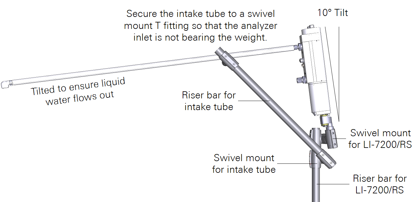
The mounting kit (part number 7900-340) includes a cross-over fitting, riser bar, and swivel mount. The head should be tilted at a 10 to 15° angle toward the inlet to ensure that water can flow out of the intake tube and analyzer optics. If the intake tube is longer than 15 cm, it should be attached to a secure element so that the analyzer inlet is not bearing its full weight.
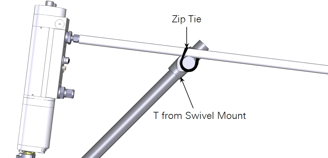
Securing the intake tube
We recommend that you secure the intake tube on the riser bar before tightening it to the sensor head. This will help prevent excessive stress on the joint where the intake tube is attached to the sensor head.
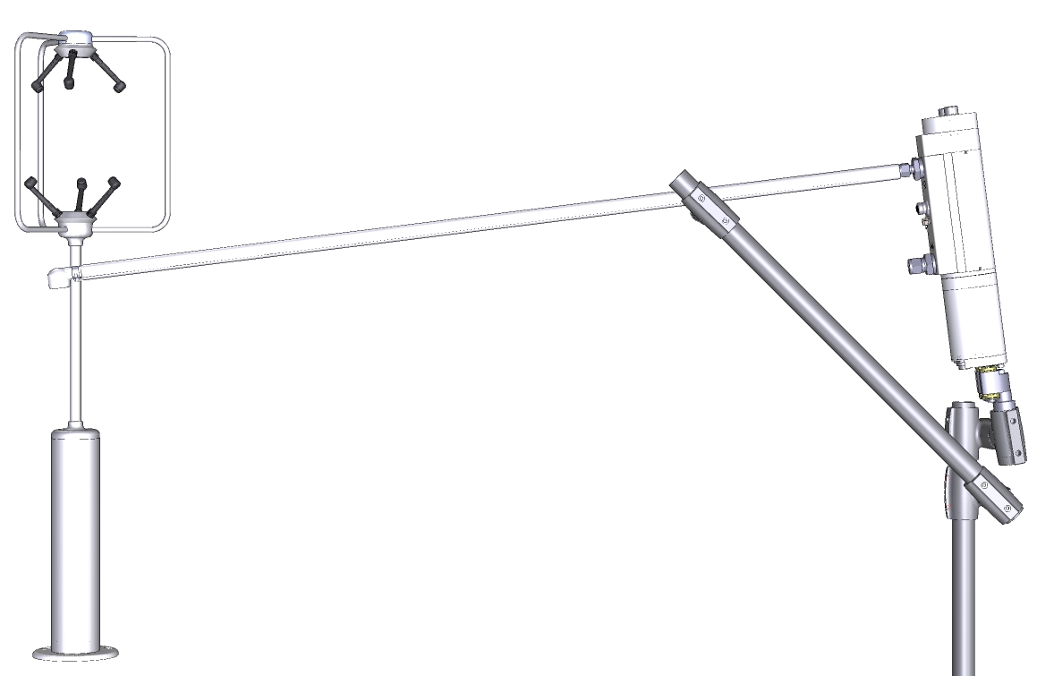
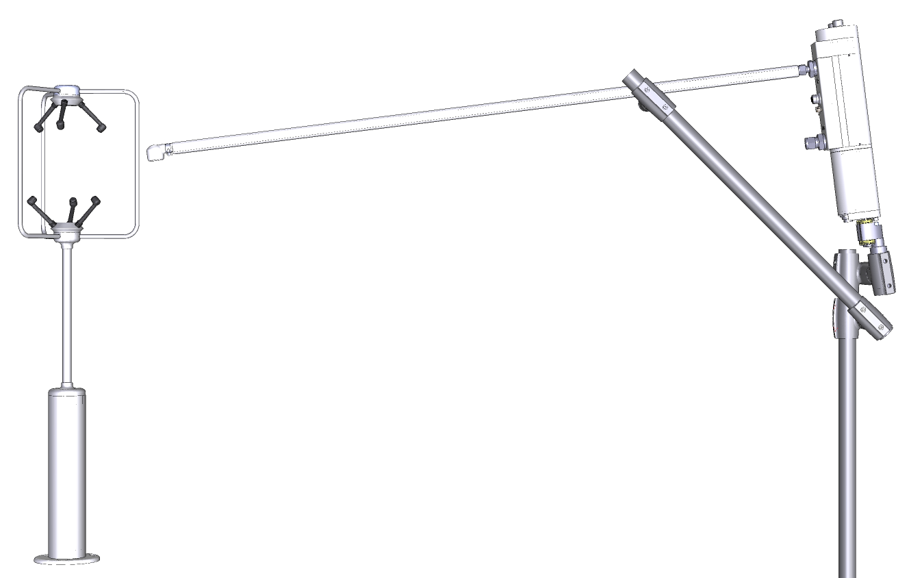
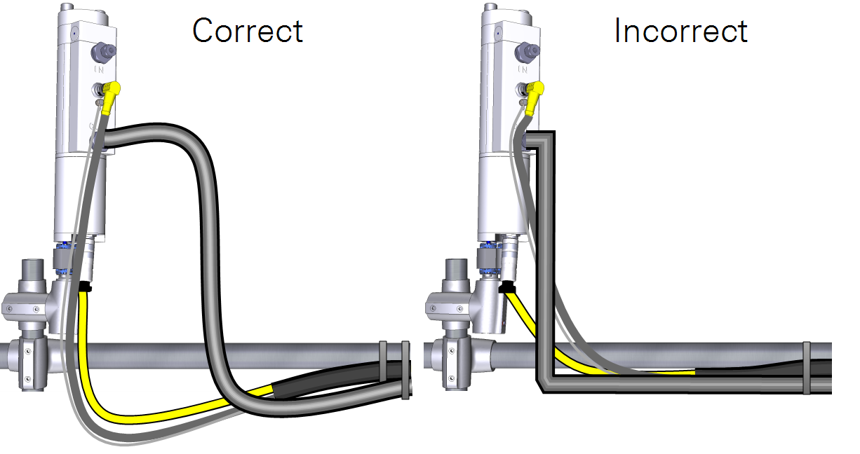
Position the intake to minimize vertical and horizontal separation between the intake and the center of the sonic anemometer, while also minimizing distortion of the airflow. If the installation is high above the top of the plant canopy (1.5-2.0 m or higher), mount the intake under the sonic path to minimize the horizontal sensor separation and wind flow disturbance, as shown in Figure 4‑2. If the installation is closer to the plant canopy top, mount the intake alongside the sonic path to minimize the vertical sensor separation, as shown in Figure 4‑3. In this case, avoid bringing the intake too close to the sonic path to minimize wind flow disturbance.
Important: Do not insert the air inlet into the anemometer path, because significant flow disturbance to all three wind components may occur, severely affecting flux data quality.
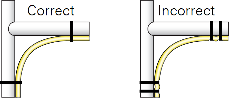
The insulated intake tube can be bent to accommodate most mounting arrangements. Use a loose bend radius to prevent kinks. Kinks will cause flow to be restricted.
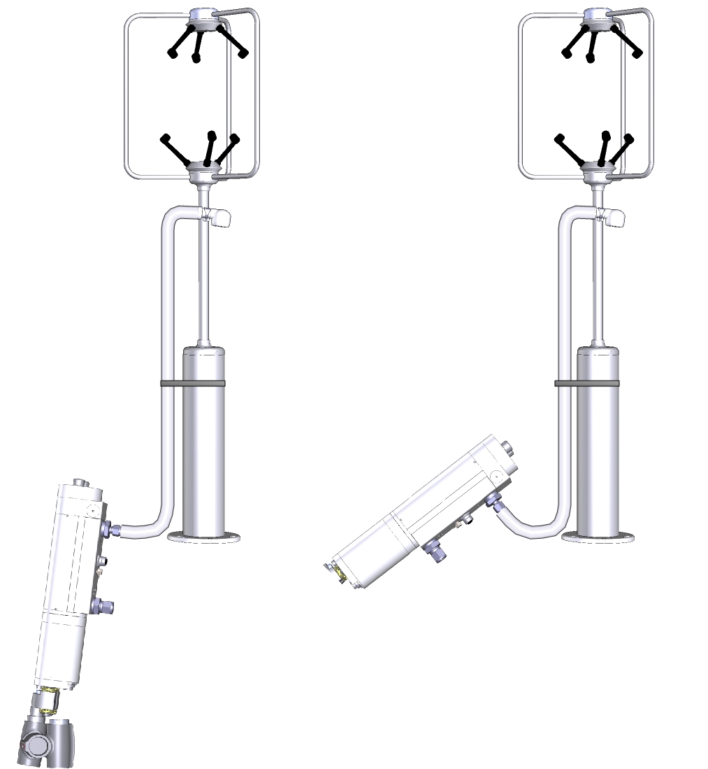
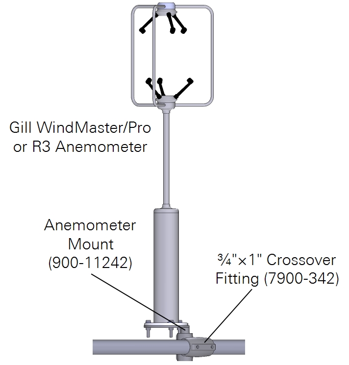
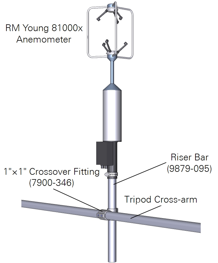
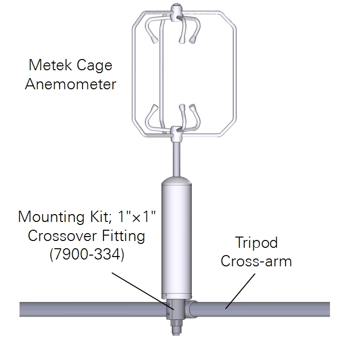
Mounting with mast-style anemometers
Basic installation for the Gill WindMaster/Pro or R3, RM Young 81000x, and Metek Cage in Figure 4‑5.
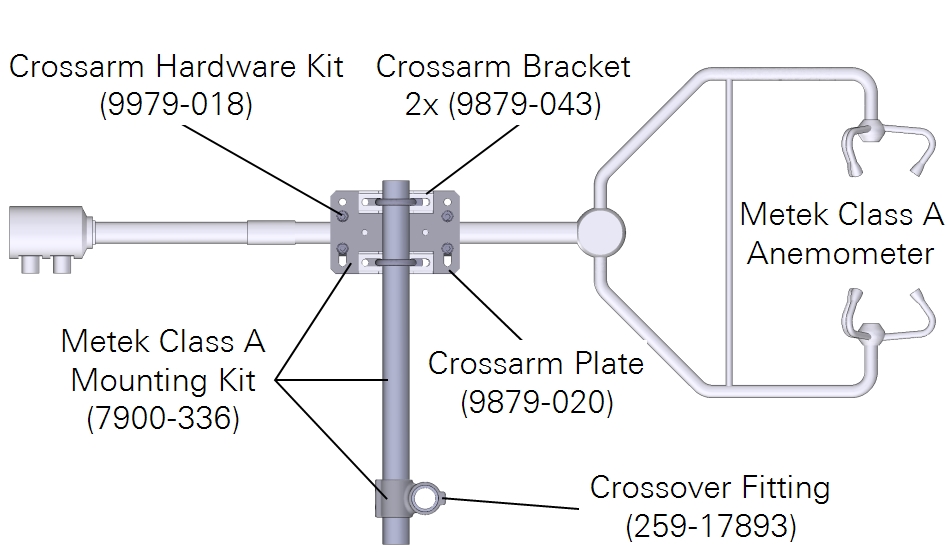
Mounting with c-clamp style anemometers
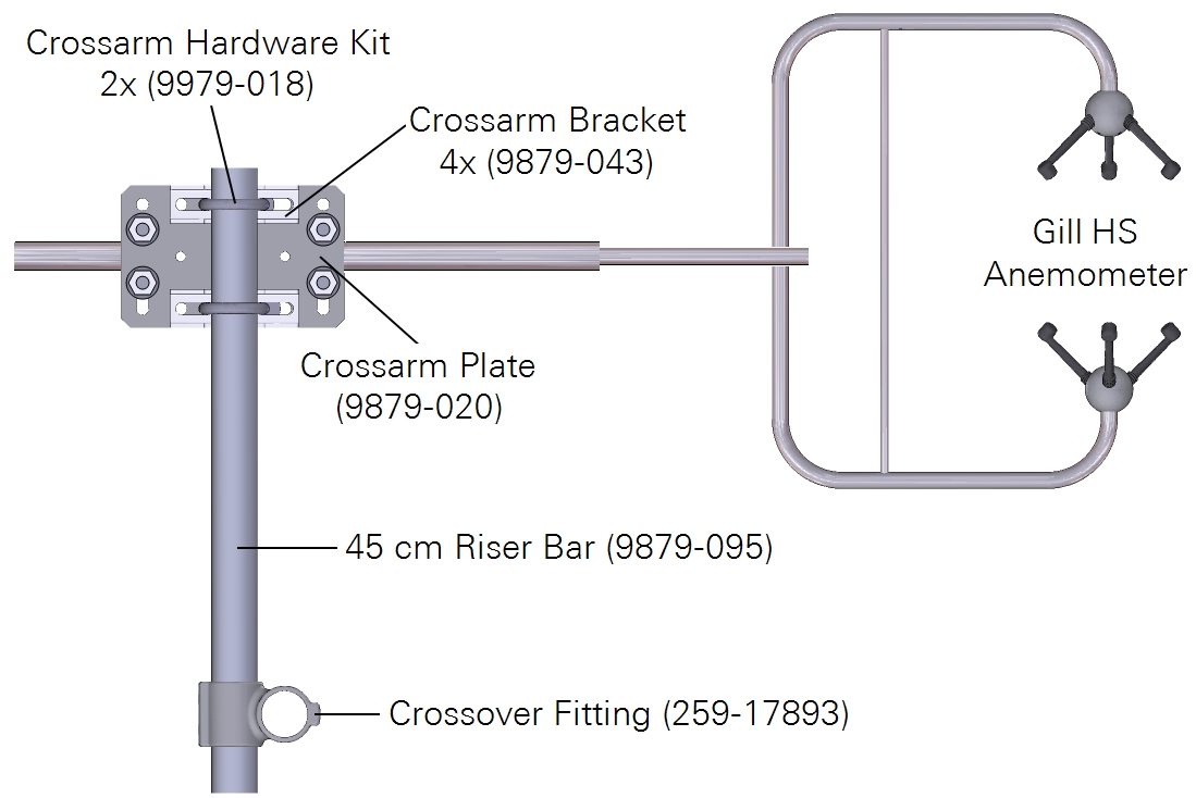
Mounting hardware is available for common c-clamp style anemometers, including the Metek Class A and Gill HS are in Figure 4‑6.
Mounting the LI-7550 and the flow module
Two mounting kits (part number 9979-022) are provided to mount the LI-7550 and the flow module to a tripod or other post. You can also attach the box directly to a flat surface. Both the LI-7550 and flow module will operate according to specifications in direct sun.
Determine the height at which the sensor head will be mounted, and plan to mount the Analyzer Interface Unit accordingly. The head cable is 5 meters long. An extension cable can extend the total cable length to a maximum of 10 meters.
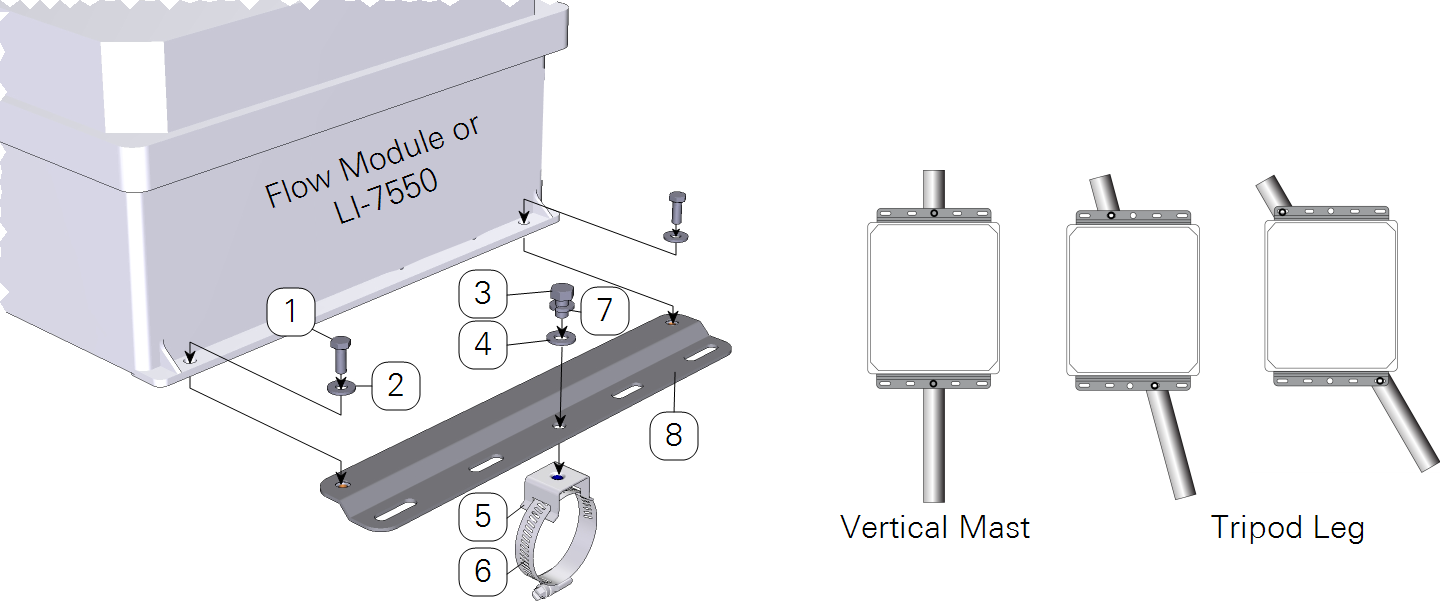
| Item | Qty. | Part Number | Description |
|---|---|---|---|
| 1 | 4 | 150-12943 | Hex Head Bolt M6x1 × 16 MM |
| 2 | 4 | 167-02054 | Flat Washer 1/4 x 5/8” |
| 3 | 2 | included w/ item #4 | Hex Head Bolt 5/16-24 × 1/2” |
| 4 | 2 | included w/ item #4 | Flat Washer 5/16” |
| 5 | 2 | 235-13234 | Flared-Leg Mounting Bracket |
| 6 | 2 | 300-13293 | Band Clamp 9/16” |
| 7 | 2 | 167-05635 | Split Washer 5/16” |
| 8 | 2 | 9879-045 | Mounting Plate |
Mounting the GPS antenna
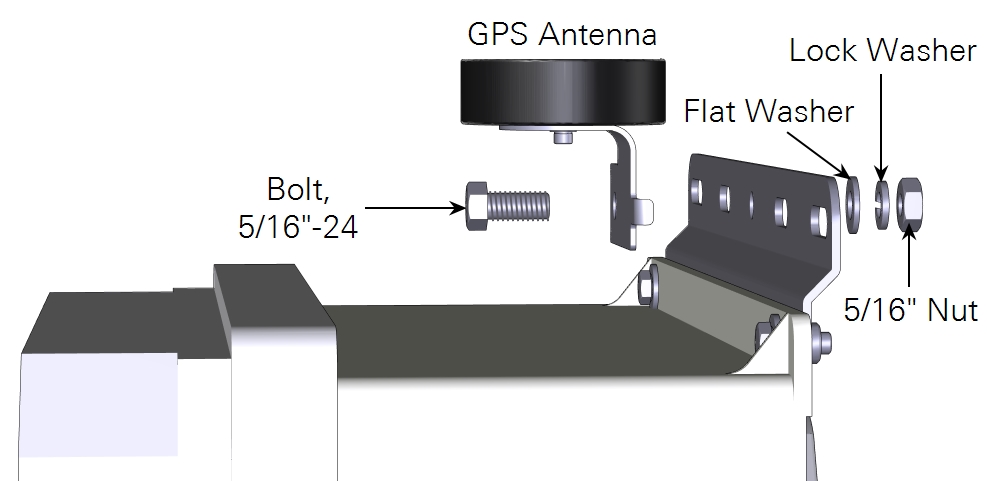
Attach the GPS antenna to the mounting plate at the top of an enclosure with the included hex head bolt.
Important: Do not install the antenna inside of an enclosure. The GPS antenna will not receive satellite signals and the system will be unable to set the clock if it is installed in this manner. For best results, but sure that the antenna has a clear, unobstructed view of the sky.
Securing the sensor head cables and tubing
It is important that the head cable be connected properly to the sensor head. Follow these guidelines:
- There is a gasket in the head cable connector that should be compressed when the cable is connected. When tightening the connector, wiggle and push the connecter while tightening to compress the gasket.
- Provide a loose bend radius to allow the cable to absorb the energy of the bending over a greater portion of its length. Use a minimum bend radius of five times the cable diameter. For the head cable, this is a 1.75” (4.5 cm) minimum bend radius (or 3.5” (9 cm) minimum loop width).
- When tying cables with cable ties, leave the ties loose enough for the cables to slide freely under the tie. Never overtighten the tie to the point where the cable jacket becomes pinched.
Collect data on the setup
The final step of the site setup is to measure a number of parameters at the site. Each of the following should be recorded for later entry into the software. These values are used in flux calculations.
Site information
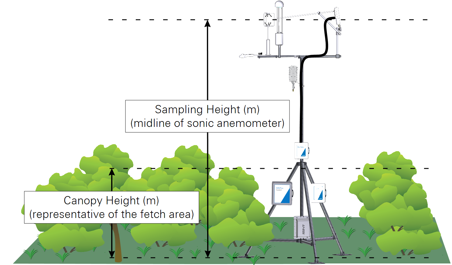
Measure both the canopy height and sampling height.
- Canopy Height (m): The distance between the ground and the top of the canopy. Since canopy height can vary from place to place, select a height that is representative of the canopy. If the canopy height changes during the sampling period, you may need update the height as the canopy grows.
- Sampling Height (m): The distance between the ground and the anemometer sample volume.
Sonic anemometer north offset
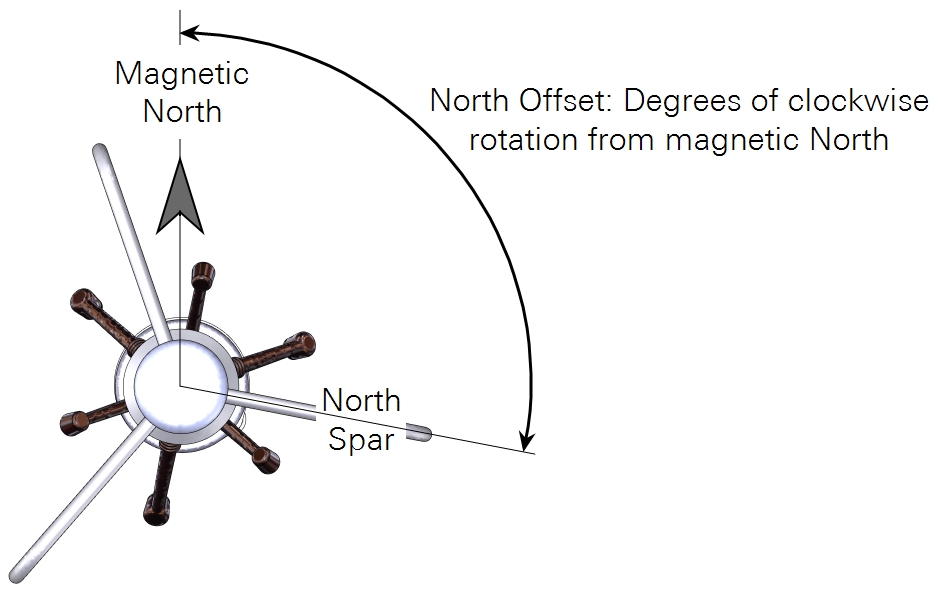
Determine the north offset of the anemometer.
- North Offset: Degrees of clock-wise rotation of the North Spar or Transducer Axis 1 from magnetic north.
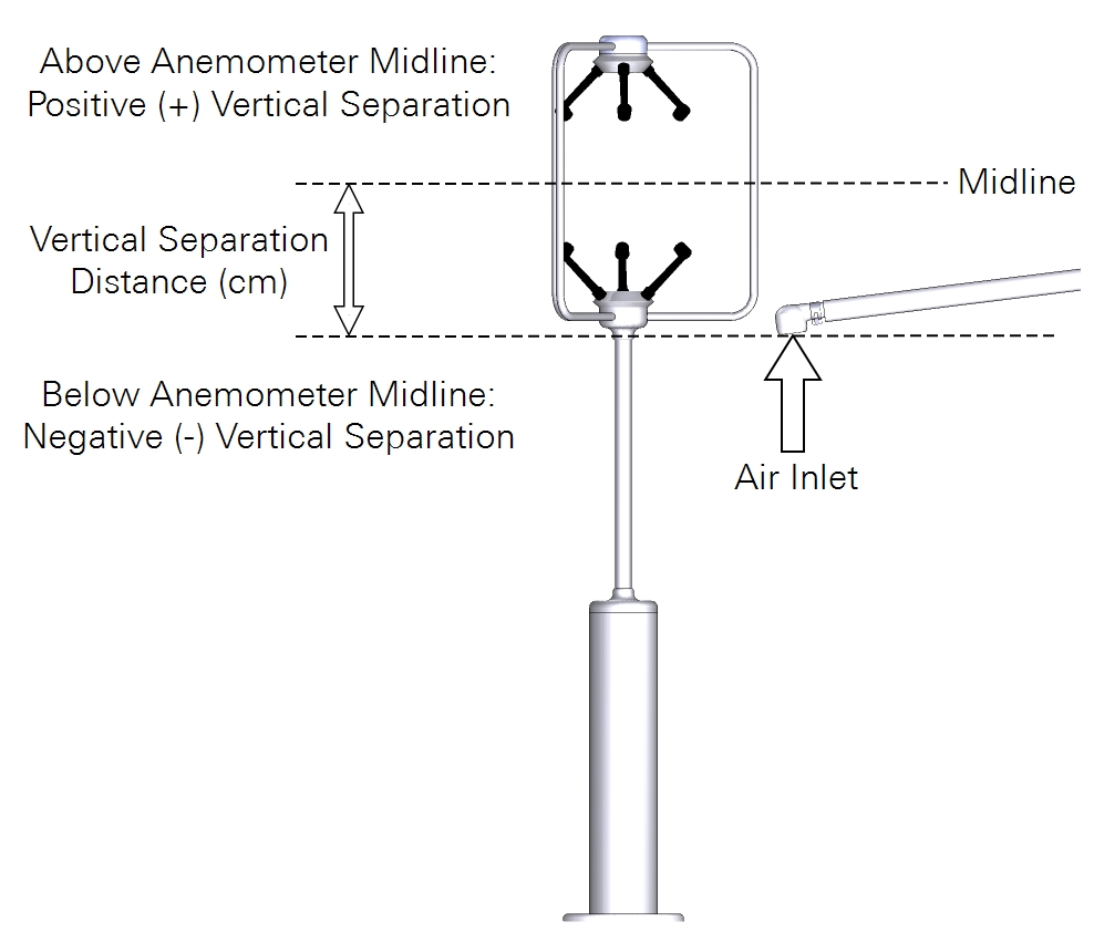
Air inlet position
Measure the north, east, and vertical offsets.
- Northward Separation (cm): North (positive) or south (negative) distance between the anemometer sample volume and the gas analyzer air inlet.
- Eastward Separation (cm): East (positive) or west (negative) distance between the anemometer sample volume and the gas analyzer air inlet.
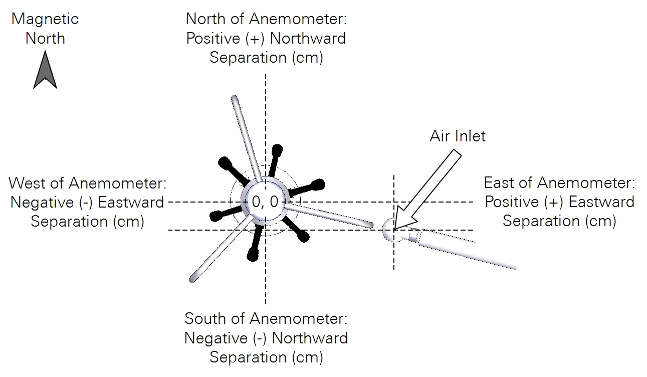
- Vertical Separation (cm): Distance between the anemometer midline and the gas analyzer air inlet. Positive value if the inlet is above the anemometer midline; negative value if the inlet is below the anemometer midline.
Intake tube parameters
Determine the Intake tube length (cm): If you have customized the intake tube, measure its length. Otherwise, one of the following lengths will apply:
- Insulated intake tube with inlet: 106.3 cm
- Insulated intake tube with 2-micron filter and inlet: 114.2 cm
- Heated intake tube with inlet: 75.8 cm
Inner tube diameter (mm): If using the insulated intake tube or heated intake tube, the inside diameter is 5.334 mm.