Configuring the eddy covariance system
The following section describes how to configure the system. To connect to the instrument with a PC, see Initial configuration.
Configuring the site setup
Site setup includes a number of settings related to log files, site information, and instruments at the site.
Configuring the USB log file
Click Site Setup > USB Log File to configure datalogging.

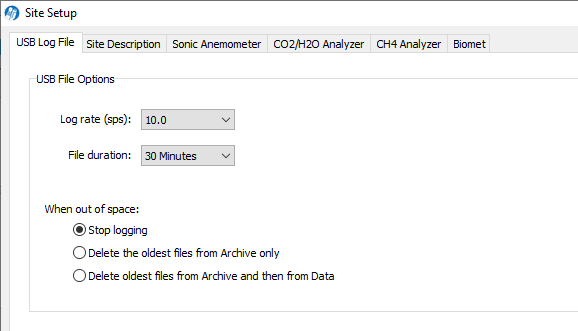
- Log Rate (sps; samples per second): 10.0, typically. Logging rates of 5, 10, or 20 sps may be acceptable in eddy covariance measurements, depending on site characteristics.
- File Duration (mandatory): 30 Minutes. EddyPro prefers 30 minute data files.
- When out of space: Select your preference for managing data when the USB drive becomes full.
Note: Files are split based on the instrument clock. With a file duration of 30 minutes and logging starting at 10:22, the file will be split at 10:30, 11:00, etc.
All files are assigned a name using the timestamp with the format YYYY-MM-DDTHHMMSS_InstrumentName.ext, where date and time are year, month, day, and HHMMSS in 24-hour time (e.g., hour 15 is 3:00 p.m.). The file extension appended is either .data, .metadata, .status, or .ghg.
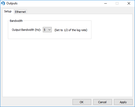
Checking the bandwidth
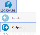
Under LI-7x00x > Outputs > Setup, verify that the Bandwidth is 1/2 of the log rate. The setting should be applied automatically when you set the Log rate (sps). For example, when logging 10 samples per second, the bandwidth should be set to 5 Hz.
Entering the site description
Under Site Description, enter information about the site. This information is written in the metadata file that is used for flux processing.
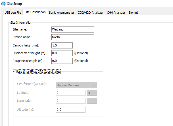
- Site name: Name of the research site.
- Station name: Name of the flux stations within the site.
- Canopy height (mandatory): Site canopy height; meters.
- Displacement height: Also referred to as zero plane displacement height, the displacement height of a vegetated surface (d) is the height at which the wind speed would go to zero if the logarithmic wind profile was maintained from the outer flow all the way down to the surface (that is, in the absence of vegetation). In other words, it is the distance over the ground at which a non-vegetated surface should be placed to provide a logarithmic wind field equal to the observed one. For forest canopies, the displacement height is estimated to vary between 0.6 and 0.8 times the height of the canopy. If not entered explicitly, EddyPro computes displacement height as d = 0.67 × canopy height.
- Roughness length: In the logarithmic wind profile, the roughness length is the height at which wind speed is zero (indicated by z0). It provides an estimate of the average roughness elements of the surface. With vegetated surfaces, because the vegetation itself provides a certain roughness, the logarithmic wind profile goes to zero at a height equal to the displacement height plus the roughness length. If not entered explicitly, EddyPro computes roughness length as z0 = 0.15 × canopy height.
- Use SmartFlux GPS Coordinates (mandatory): Uses GPS location from the SmartFlux System for the station location. When selected, the remaining settings are configured automatically.
Note: If you are testing the SmartFlux System in a building, the GPS signals may be too weak for the system to set the location. The system will get this information whenever it gets adequate GPS signals.
- GPS format (WGS84): Latitude and longitude coordinates are automatically detected by the SmartFlux System or they can be entered manually.
| Format | Description | Example |
|---|---|---|
| DDD MM SS.SSS | Degrees, minutes and seconds with North, South, East, or West suffix | 12°20’44” N, 98°45’55” W |
| DDD MM.MMM | Degrees and decimal minutes with North, South, East, or West suffix | 12°20.736’ N, 98°45.924’ W |
| Decimal Degrees | Decimal degrees with negative numbers for South and West | 12. 3456, -98.7654 |
- Latitude (mandatory if "Use GPS Coordinates" is not selected): Site latitude.
- Longitude (mandatory if "Use GPS Coordinates" is not selected): Site longitude.
- Altitude (mandatory if "Use GPS Coordinates" is not selected): Altitude (meters) at the base of the tower.
Entering anemometer information
Under Sonic Anemometer, enter information about the sonic anemometer, including the manufacturer, model, data output format, offset from true north, and height. Some of the available options (e.g., North Alignment) will change, depending on which model is selected.
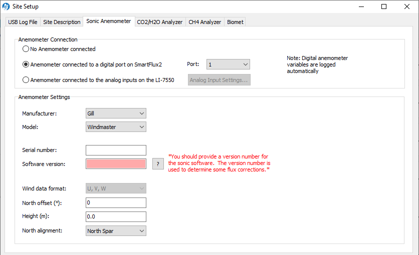
Anemometer Connection
Important: It is mandatory to select one of the connection types. For the SmartFlux® 2 System, select Anemometer connected to digital port on the SmartFlux 2.
- No Anemometer connected: Select this option if you want to operate the SmartFlux System without an anemometer.
- Sonic connected to a digital port on SmartFlux 2: Choose this option if the anemometer is connected to the SmartFlux 2 System.
- Port (mandatory with SmartFlux 2 System): Choose the port to which the anemometer is connected (1 recommended).
- Sonic connected to the analog inputs on the LI-7550: Choose this option if the anemometer is connected to analog inputs on the LI-7550 Analyzer Interface Unit.
Anemometer Settings
- Manufacturer: Choose the sonic anemometer manufacturer and model in the menus. The gas analyzer supports the following sonic anemometer models with either digital or analog inputs:
| Anemometers for use with SmartFlux 2 | |
|---|---|
| Manufacturer | Model(s) |
| Campbell Scientific | CSAT3, CSAT3B |
| Gill Instruments | WindMaster/Pro, HS-50, HS-100, or R3-50 |
| Metek | uSonic-3 Class-A MP, uSonic-3 Cage MP |
| RM Young | 81000V, 8100RE, 8100VRE |
| Anemometers for use with LI-7550 Analog Inputs Only | ||||
|---|---|---|---|---|
| Manufacturer | Model(s) | |||
| Campbell Scientific | CSAT3 | |||
| Gill Instruments | HS-50, HS-100, R2, R3-50, R3-100, WindMaster/Pro | |||
| Metek |
uSonic-3 Class A (or USA-1 Standard) uSonic-3 Scientific (or USA-1 Fast) |
|||
| R.M. Young | 81000 | |||
- Serial Number and Software Version: These fields are important because they are used to determine some flux corrections. See the EddyPro® instruction manual or online help for more information.
- Wind data format (optional): From the three axis velocities, the wind speed is calculated, and output as either signed U, V, and W, as Polar and W, or as raw velocity values. The units of output are set during the anemometer configuration. Choose the wind data format from the menu:
-
- U, V, W (some Gill anemometers): U is the direction aligned with the north spar. V is the direction 90° counter-clockwise from the N/Reference spar. W is vertical.
- Polar, W - The wind speed in the UV plane, with direction in degrees clockwise from 0 to 359°, with respect to the Reference spar (normally aligned to North). Note: This option is not supported for Gill anemometers.
- Axis velocities - Raw velocity values for U, V, W.
- North offset (°) (mandatory): Offset, in degrees (0-359°) from which the Reference spar/axis or orientation of the anemometer varies from geographic/magnetic north.
Important: EddyPro requires the offset with respect to geographic north as two pieces of information: The offset with respect to geographic north and the magnetic declination. Currently the software does not provide an entry for magnetic declination. For the best results, enter the North Offset to magnetic North. This will create small differences in the wind direction between EddyPro and SmartFlux results (a constant offset equal to the magnetic declination), but the flux results will be the same, if all other settings are the same.
- Height (m) (mandatory): Sonic anemometer height above the ground, in meters, measured to center of the anemometer sample volume.
Entering CO2/H2O analyzer information
Under CO2/H2O Analyzer, enter the gas analyzer position relative to the sonic anemometer and select the values to log.
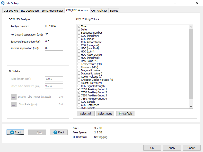
The distance between the gas analyzer and sonic anemometer is used to estimate the high-frequency flux losses. Distances are provided in a Cartesian coordinate system, which allows EddyPro to determine the distance from a gas analyzer and the anemometer.
Important: At least one separation must be different from 0. Values are measured at the site and are relative to the sonic anemometer. Entering wrong values will result in incorrect flux calculations.
- Measurements must be provided in the indicated units.
- The anemometer is the center (0, 0) of the coordinate system.
- For all gas analyzers, the distances from the reference anemometer are provided along the north-south east-west axes.
Separation values are specific to the site setup. See Site information.
- Northward Separation (cm) (mandatory): North or south distance between the LI-7500RS sample path and the anemometer.
- Eastward Separation (cm) (mandatory): East or west distance between the sample path and the anemometer.
- Vertical Separation (cm) (mandatory): Vertical distance between the sample path and the anemometer.
Selecting CO2/H2O log variables
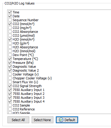
Select variables to log under CO2/H2O Log Values.
- Click Select All to record the full set of raw data, including absorptance values. This takes more storage space, but provides the most information on the instrument performance.
- Click Default select the minimum set of variables for flux computations. This is recommended if you need to maximize data storage space (e.g., you are unable to retrieve data from the site on a regular basis).
Click OK or Apply to implement the settings.
Entering CH4 analyzer information (optional)
If the system is connected to an LI-7700 Open Path CH4 Analyzer, under Site Setup > CH4 Analyzer, specify the separation between the sonic anemometer and the LI-7700 sample volume and select variables to log.
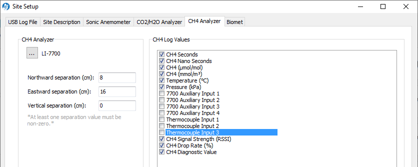
Important: At least one separation must be different from 0. Values are measured at the site and are relative to the sonic anemometer. Entering wrong values will result in incorrect flux calculations.
- Northward Separation (cm) (mandatory): North/south distance between the LI-7700 Analyzer and the anemometer. Positive values if north and negative values if south of the anemometer.
- Eastward Separation (cm) (mandatory): East/west distance between the LI-7700 Analyzer and the anemometer. Positive values if east and negative values if west of the anemometer.
- Vertical Separation (cm) (mandatory): Vertical distance between the LI-7700 Analyzer and the anemometer. This value is negative if the center of the LI-7700 sample volume is below the center of the reference anemometer sample volume and positive if the gas sample is above.
Selecting CH4 log variables (optional)
Under Site Setup, click the default button ( ) to select the recommended variables for processing. Or, click Select All to log all variables.
When you start logging data the selected variables for the LI-7700 will be logged with the dataset.
The LI-7700 data values to be logged to the USB drive are chosen under CH4 Log Values. In addition, you can enable the Log LI-7700 status records (.status) check box to collect LI-7700 STATUS records. This is for diagnostic purposes.
Begin logging data
Start, Stop, and Eject buttons are on the main dashboard and on each tab under the Site Setup menu.
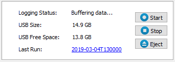
Click Start to begin logging data. Data logging will begin automatically when a suitable USB drive is inserted into the SmartFlux System and any time the instrument restarts. Click Stop to quit logging.
Always eject the USB drive before removing it. After pressing the Eject button, the LED inside the SmartFlux System will turn off when it is safe to remove the drive.
Verifying flux computations
To verify that fluxes are calculated, review the data after at least 30 minutes of data have been logged and processed. View the results under the Results graph in the software dashboard. To get a better idea of system performance, review 24 hours of data.
- System status information is summarized in System diagnostics. Review this to get a general idea of the system performance.
- Data download options are described in Automatic file management and Copying data files from USB storage
- Data files are described in Viewing and evaluating data.