Analog inputs (LI-7700)
The LI-7700 has 4 analog input channels and three thermocouple channels. These can by used with either the optional 7550-101 Auxiliary Sensor Interface or the Analog Input/Output Cable (part number 392-10109). The 7550-101 is a weatherproof terminal strip that provides sealed electrical connections. The Analog Input/Output Cable terminates with bare leads on one end and a Turck connection on the other. It is included with the LI-7550 Analyzer Interface Unit and available as an optional accessory.
The 7550-101 Auxiliary Sensor Interface and the Analog Input/Output Cable can be used in three ways:
- Connect four analog data sources and three thermocouple inputs to the LI-7700.
- Connect four analog data sources to the LI-7550 Analyzer Interface Unit.
- Distribute the 6 analog outputs of the LI-7550.
Here we describe how to use the 7550-101 or the Analog Input/Output Cable for analog inputs on the bottom of the LI-7700.
Configuring auxiliary inputs
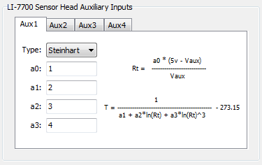
Analog inputs are configured from the Configure Auxiliary Inputs dialog box. Auxiliary inputs 1 through 4 are used with LI-7700 inputs. They are configured with the top four tabs in the Configure Auxiliary Inputs window. One of two mathematical conversions can be applied to the input voltages: 1) a third order polynomial or 2) a Steinhart equation (for computing temperature in °C from a thermistor).

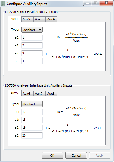
The polynomial can be used to scale inputs from a variety of sensors. Below is an example demonstrating ways that the polynomial and Steinhart equation can be used.
Wiring an air temperature sensor into the 7550-101: Set the Type: to Steinhart.
For the 1400-101, 1400-102, or 8100-203 temperature sensors, use the following coefficients to log temperature as °C:
| LI-7700 Auxiliary Channel | Aux1 | |
|---|---|---|
| Polynomial Values (set in LI-7700 software) |
a0 | 100,000 |
| a1 | 1.1259 e-3 | |
| a2 | 2.3459 e-4 | |
| a3 | 8.6329 e-8 | |
Connect the black lead to a +5V terminal, the red lead to one of the auxiliary input terminals (AUX1, AUX2, etc.), and leave the orange lead disconnected.
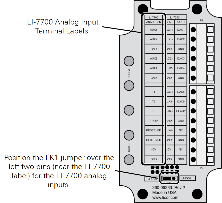
Terminal connections
Loosen the four Philips head screws in each corner of the Auxiliary Interface Box module and remove the top cover. There is a small jumper located at the LK1 label; when using the 7550-101 with the LI-7700 (Option 1), position the jumper over the 2 pins nearest the LI-7700 label (the lower two pins in Figure 2‑8).
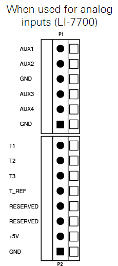
There are two terminal strips, with connections that can be used for inputs or outputs. The terminal positions are numbered and configured as follows:
| Option 1 | ||||
|---|---|---|---|---|
| 7550-101 Auxiliary Sensor Interface | Description | Analog In/Out Cable(p/n 392-10109) | ||
| Terminal | Input | Wire Color | Pin | |
| 1 | AUX1 | Auxiliary Input 1 Signal | White | Pin 1 |
| 2 | AUX2 | Auxiliary Input 2 Signal | Brown | Pin 2 |
| 3 | GND | Ground | Tan | Pin 10 |
| 4 | AUX3 | Auxiliary Input 3 Signal | Green | Pin 3 |
| 5 | AUX4 | Auxiliary Input 4 Signal | Yellow | Pin 4 |
| 6 | GND | Ground | Tan | Pin 10 |
| 7 | T1 | Thermocouple 1 Signal1 | Gray | Pin 5 |
| 8 | T2 | Thermocouple 2 Signal1 | Pink | Pin 6 |
| 9 | T3 | Thermocouple 3 Signal1 | Blue | Pin 7 |
| 10 | T_REF | Thermocouple Reference1 | Black | Pin 11 |
| 11 | Reserved | Thermistor Input | Red | Pin 8 |
| 12 | Reserved | Thermistor Reference | Violet | Pin12 |
| 13 | +5V | +5V Supply (10 mA max.) | Orange | Pin 9 |
| 14 | GND | Ground | Tan | Pin 10 |
Connecting sensors
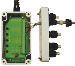
There are five “gland” type plugs on the Auxiliary Sensor Interface top cover that secure and seal the wires that are connected to terminals inside the box. To attach your sensor(s) to the Auxiliary Sensor Interface, follow these steps:
- Remove the #1 Philips screws from each of the four corners of the Auxiliary Sensor Interface and remove the top cover.
- Remove the cap from a gland plug by turning the cap counterclockwise.
- Pass the wires through the top of the plug cap, rubber grommet, and then through the gland plug.
- Use a small standard screwdriver to loosen the appropriate screw terminals and insert the wire leads into the terminals. Tighten the screw terminals to secure the wires. Make a note of which plug the wires are passing through and which terminals the wires are connected to. This will be needed later when you configure the sensor coefficients in the software.
- Insert the grommet into the gland plug and pull gently on the wires to remove slack from inside the interface. Attach additional sensor wires to the appropriate terminals.
- When you have finished installing all of your sensors, re-attach the interface top cover and tighten the gland plug caps.
- Attach the Auxiliary Sensor Interface cable connector to the Analog Input connector on the LI-7700 connection panel.
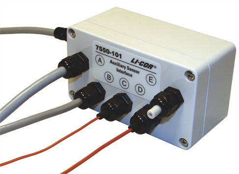
There are 5 plastic plugs in the interface box gland plugs and 10 extras (part number 300-07393) in the spares kit. These should be inserted into unused gland plugs on the Auxiliary Sensor Interface. The plugs prevent foreign materials (e.g., water, insects, dirt) from entering the interface box. Insert the narrow end of the plug through the gland plug and tighten the plug cap (as shown in plug E above). The plugs should always be used in any gland plug that does not have a wire.
There is also a length of Santoprene® tubing in the Auxiliary Sensor Interface spares kit. This tubing can be cut to length and placed around small gauge wires that may not be able to be tightened sufficiently with the gland plugs. It can also be used for oddly shaped wires that can be difficult to seal with the gland plug caps, as in plugs C and D above.
Thermocouple inputs
The thermocouple inputs are designed to work with Type E thermocouples (chromel-constantan). The positive (+) thermocouple wire (chromel, purple insulation) should be connected to T1, T2, or T3. The negative (-) thermocouple wire (constantan, red insulation) should be connected to the T_REF. All three channels share a common connection T_REF. The range of thermocouple temperature measurements is ±20 °C from the reference temperature inside the Auxiliary Sensor Interface.
Thermocouple readings can be influenced by rapid changes to the temperature or by heat loads to the auxiliary sensor interface. To avoid risk of these issues, shield the auxiliary sensor interface from direct sun and/or thermally insulate the apparatus. A simple solution is to wrap the Auxiliary Sensor Interface with aluminum foil.
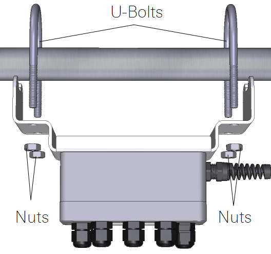
Mounting the 7550-101 Auxiliary Sensor Interface
The Auxiliary Sensor Interface has an attached mounting plate that can be used to attach the interface to a 1” to 1½” (2.5 to 3.8 cm) diameter post. Two U-bolts and four nuts are included in the 7550-101 spares kit. These can be used to attach the Auxiliary Sensor Interface as shown in Figure 2‑9. It can be mounted vertically or horizontally. If you do not want to use the attached mounting plate, remove the top cover of the box and remove the two screws (in opposite corners) that secure the box to the bracket. You can then secure the interface using wire, cable ties, or other methods of your choosing.