Data files
File header
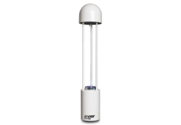
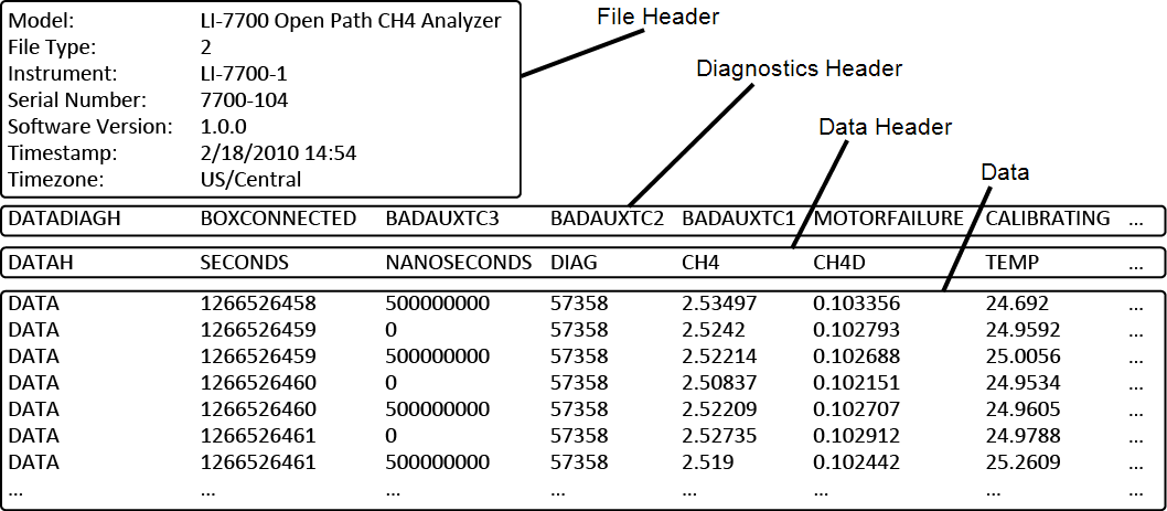
The header is part of every data file produced by the LI-7700. It includes the following fields:
| Header Label | Description |
|---|---|
| Model: | Analyzer |
| File Type: | Header content descriptor (usually 2) |
| Instrument: | Instrument name |
| Serial Number: | Instrument serial number |
| Software Version: | Instrument firmware version |
| Timestamp: | Date and time the file was created |
| Timezone: | Time zone setting in the instrument |
Diagnostics header
If the Diagnostics check box was checked in the PC, USB, or RS-232 outputs, a diagnostic header and column is included in each data file. The Diagnostics Header is a list of potential diagnostics that are output with each file. The DIAG column contains diagnostic values affiliated with each record in the file, and these values encode one or more pieces of diagnostic information. Each value is an integer between 0 and 65535, which can indicate up to 16 diagnostics. The following guide and example can help interpret this diagnostic information.
Interpreting a diagnostic code
If the diagnostic field has a value of 14, this indicates that readings from the thermocouples are bad. This will occur anytime a functioning thermocouple is not attached. The “14” is the sum of values in the “Integer” column from rows 2, 3, and 4 in the table above (2+4+8). If you are using an LI-7550, this value will be “15” under the same configuration.
- Identify the integer in the DIAG column of the data file.
- Find the largest value in the Integer column of Table 6‑2 which is the value from the DIAG column. The diagnosis associated with that value occurred.
- Subtract the DIAG value from the Integer. If the difference is 0, there are no other codes. Otherwise, repeat step 2 using the difference rather than the DIAG code.
- Repeat steps 2 and 3 until the difference equals 0.
- Refer to Table 6‑2 and locate the largest value that is 17231.
- This is 16384, which indicates that no laser signal was detected. Find the difference: 17231-16384=847.
- In Table 6‑2, find the largest value that is the 847.
- It is 512, which indicates that the lower mirror was spinning. Find the difference: 847-512=335.
- Find the largest value that is 335. It is 256, which indicates that the pump was running.
- Find the difference: 335-256=79.
- Find the largest value that is 79. It is 64, which indicates that the lower mirror heater was on.
- Find the difference: 79-64=15.
- Repeating the steps above, it is determined that three thermocouples were not attached or were dysfunctional, and the LI-7700 is connected to an LI-7550.
In summary, if there is a diagnostic value of 17231, the instrument was in the midst of a cleaning cycle while heating the lower mirror.
Note: Any time an odd number occurs in the DIAG field, it indicates that an LI-7550 was in use. Even numbers indicate that there was no LI-7550 attached.
Data header
The data header will include all the variables that are selected in the PC or USB logging window. A UTC time stamp (seconds and nanoseconds) is always output with each record in a file. Therefore, it is not necessary to output date and time unless you wish to have the local time stored with the file. The following list of items may be visible in the data header row, depending on which values are logged:
Data
The data is in columns below the DATAH row. The row above the data header includes a list of diagnostic codes that are output with each data file. This information is summarized by the value in the data field called DIAG. These values are described in Diagnostics header.
Note: If you choose to log status columns to the data file, status records will be interspersed with the data records by time. Only log status records if you are diagnosing the LI-7700.
When logging to a USB storage device or a host PC, you can choose to log status columns to the log file, to a separate file, or not at all. Status data can also be sent through the RS-232 output. Status data are always logged at 2 Hz. The following header is output with the status file.
| Column Heading | Description |
|---|---|
| SECONDS | Seconds in UNIX time, or the time the instrument is set to |
| NANOSECONDS | Nanoseconds |
| DIAG | Diagnostic value, an integer |
| RSSI | Signal strength (Residual Signal Strength Indicator, 0-100%) |
| REFRSSI | Reference Signal Strength (0-100%) |
| LCTSETPT | Laser cooler temperature set point (°C) |
| LCTACTUAL | Laser cooler temperature measured (°C) |
| BCTSETPT | Block cooler temperature set point (°C) |
| BCTACTUAL | Block cooler temperature measured (°C) |
| CHASSISTEMP | Temperature in lower housing (disabled) |
| OPTICSTEMP | Reference junction temperature for top thermocouple (°C) |
| OPTICSRH | Relative humidity in the upper dome (%) |
| AUXREFTEMP | Temperature of Auxiliary Sensor Interface, 7550-101 (°C) |
| MOTORSETPT | Spin motor set point (preferred alignment) |
| MOTORACTUAL | Spin motor position (actual alignment) |
| USB | Device present |
| USBCAPACITY | USB device capacity |
| USBFREESPACE | USB device free space |
| REF | A diagnostic value used in technical support |
| GND | |
| OPTICSDELTA | Temperature difference between air and upper mirror |
| CHK | A checksum feature to check the integrity of data |