If the instrument is not measuring methane or if it is showing errors, you may need to observe the diagnostics.
Laser temperature control
During normal operation, the instrument uses an automatic control loop to maintain the laser temperature, which in turn keeps the laser wavelength tuned to the absorptance feature of interest. In the LI-7700, the laser scans a sealed vessel of methane along with the open path cavity. The results of the cavity scan (reference) and optical path scan (sample) are displayed as a waveform on the Diagnostics Page of the Main View:
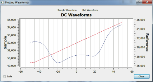
The above display indicates normal operation by the following features:
- A standard bell shaped curve for both the sample and reference paths
- Both overlay nicely, with the peak at or very near the zero point on the horizontal axis
- The waveform has sufficient depth (e.g., not too shallow vertically)
The two status indicators located in the status panel above the chart display should further support this state. Both the Laser Temperature and Reference Lock indicators should show green. If either or both are red, then the instrument is not functioning normally and it may be necessary to manually adjust the laser temperature parameters. When the laser is scanning across the desired methane absorption feature, line lock is established. Otherwise, line lock is not established and the instrument will not measure methane density.
Opening the Laser Temperature Control window
Hover the mouse pointer over the red light indicator on the status panel and click the left mouse button (the indicator must be red to complete this action). Or, press the Ctrl + Alt + L. This can be done at any time when you are connected to an instrument.
The Laser Temperature Control window will open:
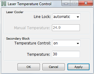
It is only possible to open this dialog when the application is connected to an instrument. As the dialog indicates, there are two temperature parameters that may be manipulated. Laser Cooler temperature is the primary one and should be altered first. In order to change the value, the Line Lock setting must be changed from Automatic to Manual, as shown below.
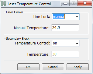
This will allow you to set the temperature manually. When you are changing the laser cooler temperature, watch the diagnostics page and see how the waveform changes as the temperature setting is increased or decreased.
Manual Line Lock example
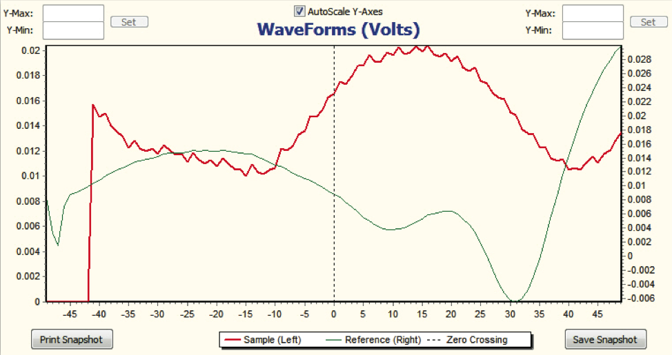
In this example, the automatic line lock was disabled and the laser temperature was manually driven from a value of 10.0 to 16.0. This resulted in the following waveform display:
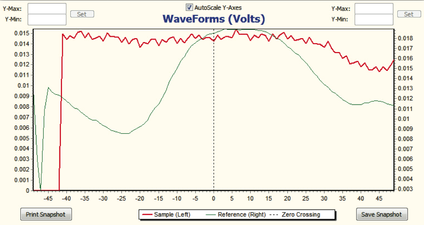
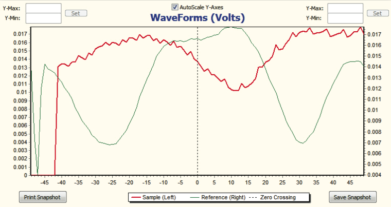
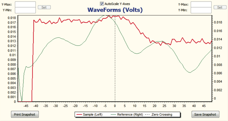
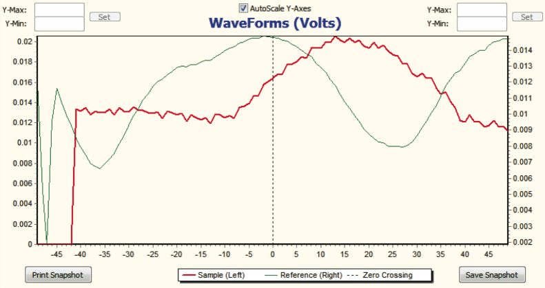
At this point, the desired positions could be either to the right or to the left. Since the line lock temperature value was known to be higher, the values were incremented in single digits (e.g., 11, 12, …, 16), and the following series of images were taken:
Re-enabling automatic line lock
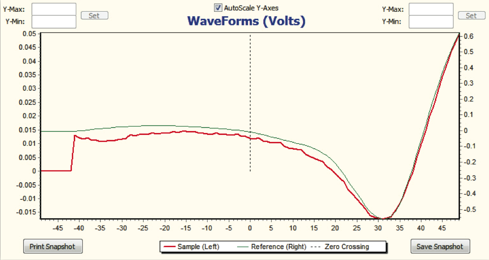
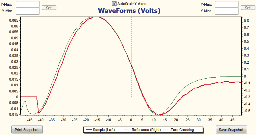
As the previous images show, the waveform is gradually shifting from right to left as the temperature parameter is increased from 10.0 to 16.0 °C. At this point, since the top of the bell shape is relatively close to the zero point on the horizontal axis, you can attempt to have the instrument re-lock automatically by setting the line lock parameter back to automatic. This should cause the wave to slide further to the right or left until the peak is at or very near the zero point. If this does in fact occur, the relocking was successful and the dialog may be closed. If not, repeat the process, or simply restart the instrument.