Field installation
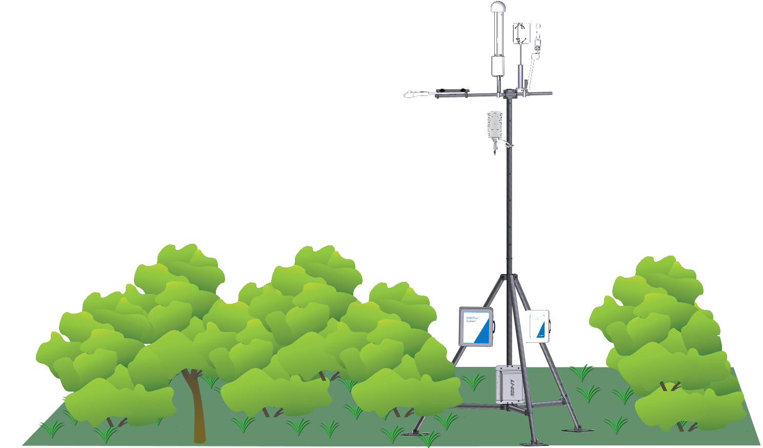
This section describes how to install the instrument and its associated components on a tower or tripod in a typical eddy covariance application.
Mounting the LI-7700
For field deployments, the LI-7700 must be firmly attached to a stable tripod or tower.
Considerations for positioning the LI-7700
There are numerous factors to take into account when deploying the LI-7700 in eddy covariance flux applications. Addressing these concerns appropriately is critical to minimizing required frequency response corrections. Two considerations addressed here are instrument height above the canopy and proximity to the sonic anemometer.
Be sure that the instrument is deployed in accordance to the guidelines set forth by the scientific community for eddy covariance data collection. Mounting the LI-7700 too close to the canopy may result in sampling in the roughness sub-layer, which is not representative of the study site. The minimum recommended height above the canopy is 1.0 to 1.5 m or more, but this will vary depending on surface roughness and other factors.
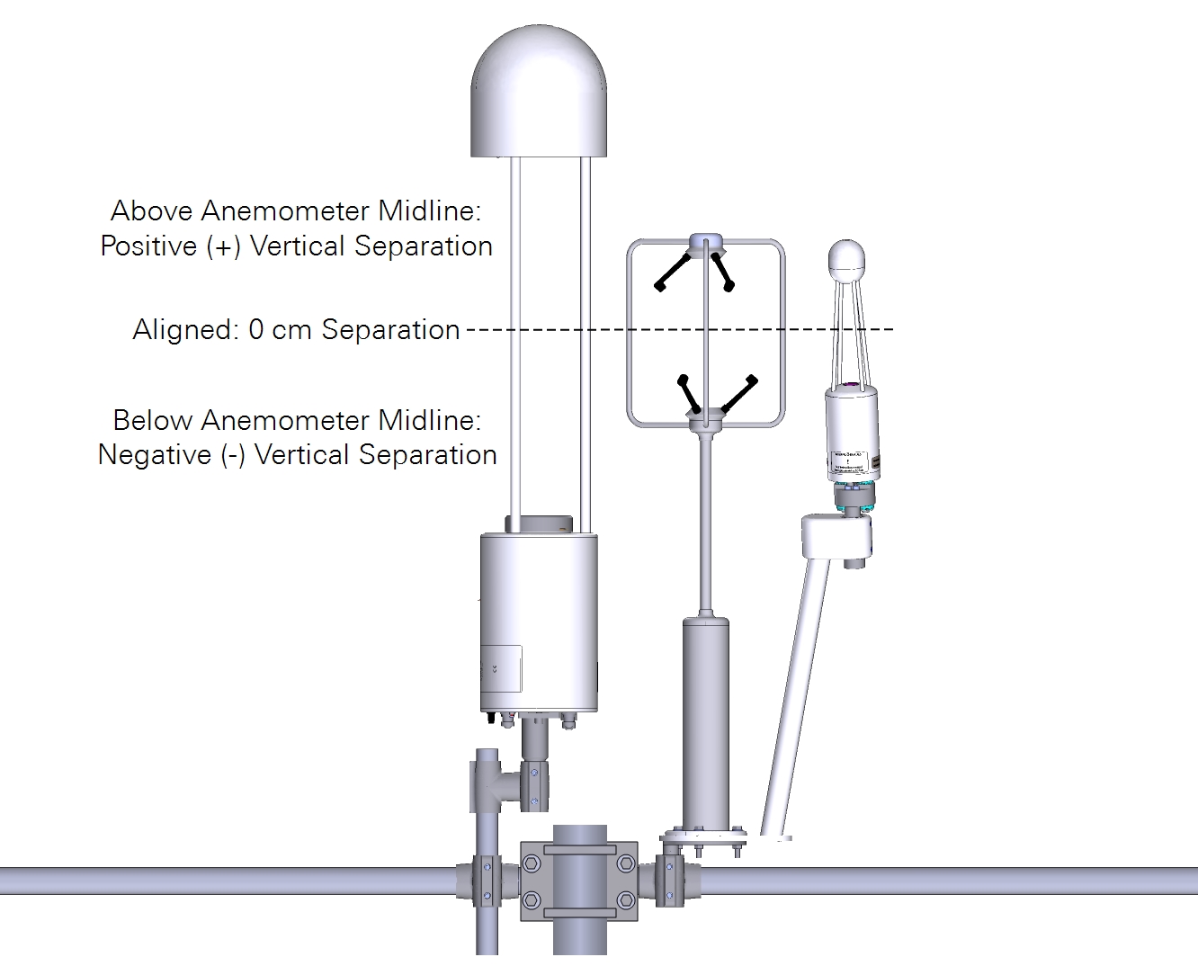
A vertical mounting orientation provides 360° acceptance for wind direction, and this is the recommended orientation. However it is oriented, the LI-7700 should be positioned as close to the sonic anemometer as practical without affecting the airflow through the anemometer.
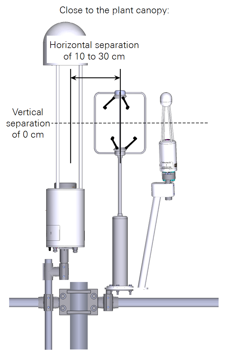
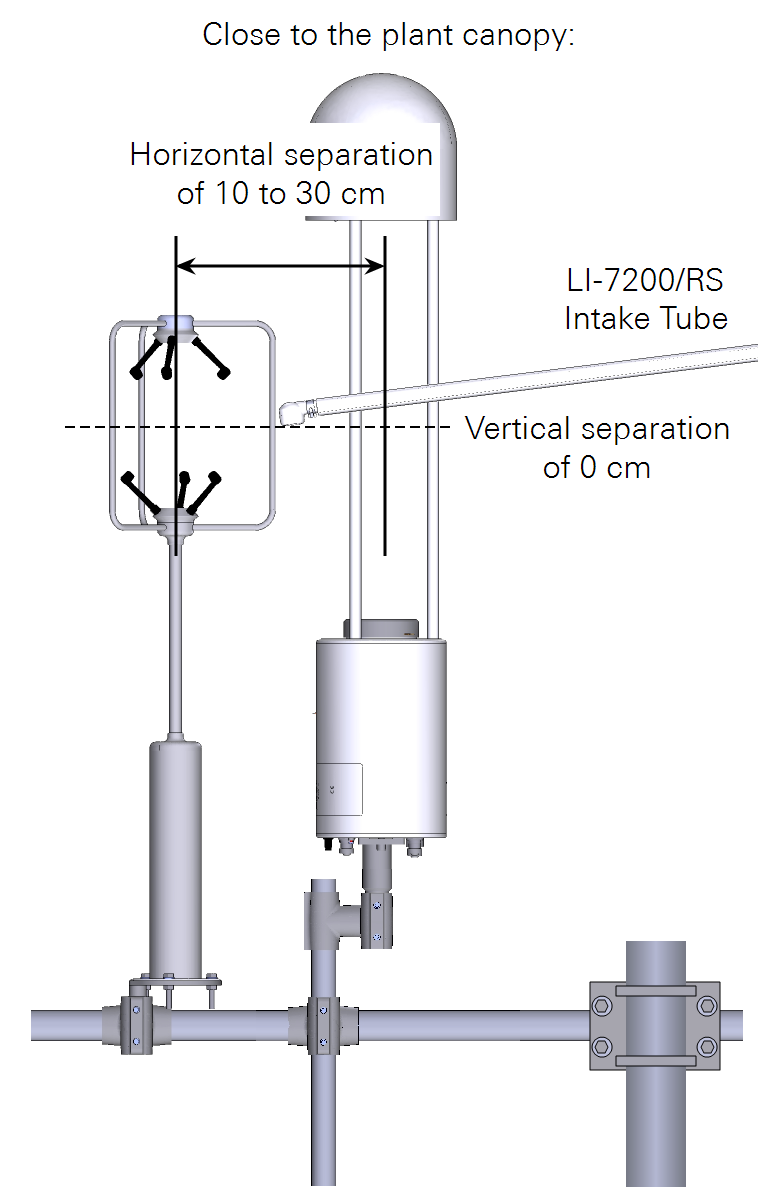
For near-surface deployments, the LI-7700 should be 10 to 30 cm horizontally from the anemometer and they should have a minimal vertical separation (see Figure 3‑1). As with all instruments in an eddy covariance flux system, the closer to the canopy, the closer the instruments must be to each other to minimize frequency response corrections for sensor separation.
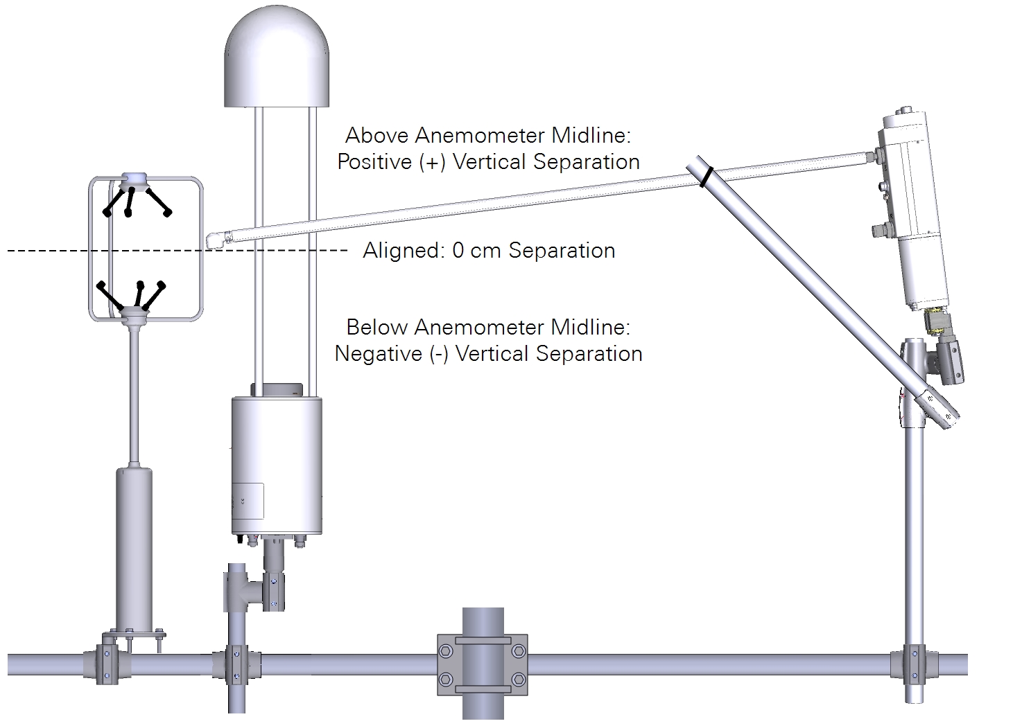
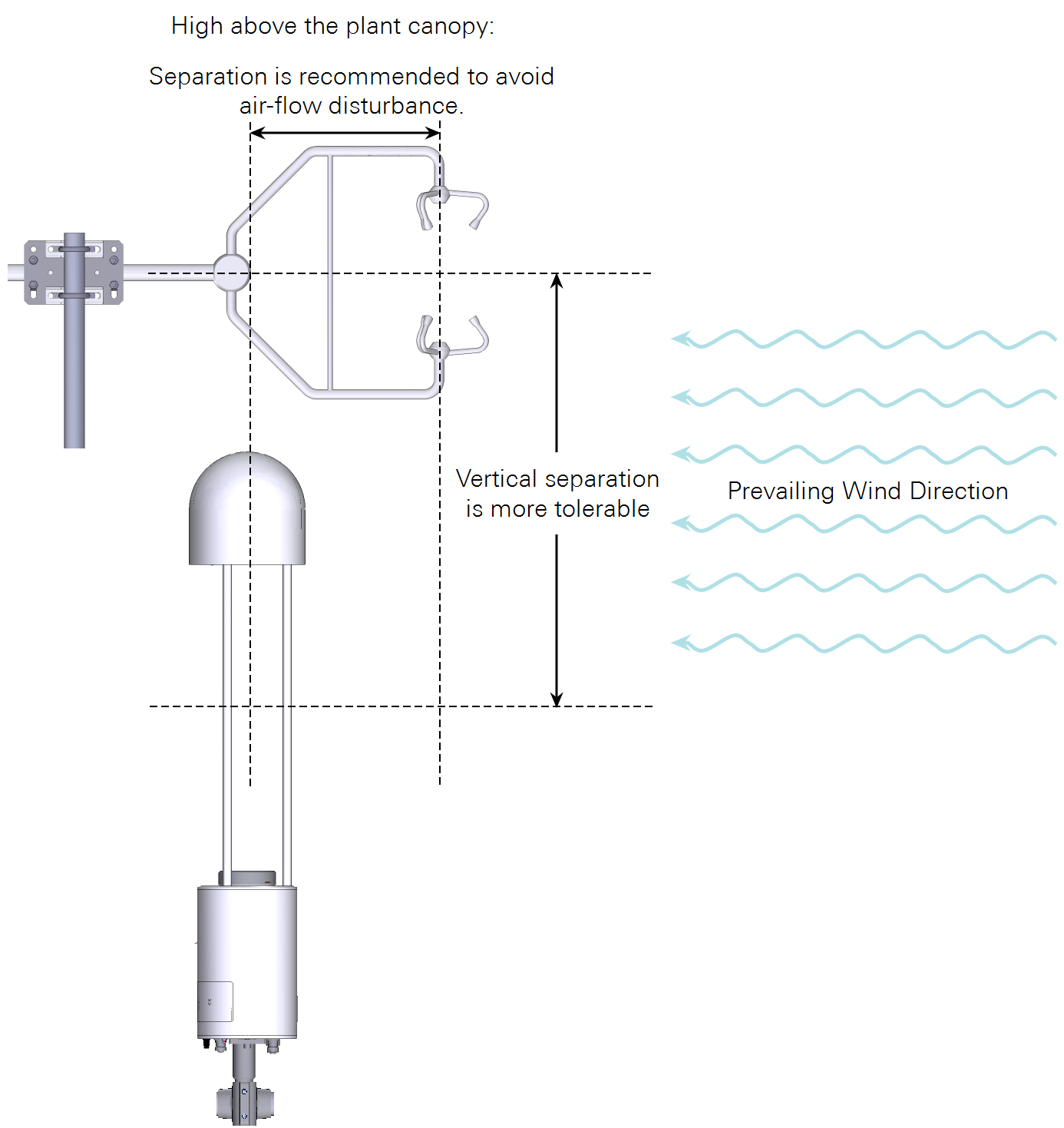
For deployments high above the canopy, the LI-7700 should still be as close as practical to the sonic anemometer, but larger vertical separations are now more acceptable. For example, at heights of 40 meters above the canopy, the anemometer sample path can be above the LI-7700 entirely (see Figure 3‑2).
Important: Never put scalar measurements (e.g., the LI-7700) above the sonic anemometer, as it may lead to errors and require difficult-to-predict corrections.
Site considerations
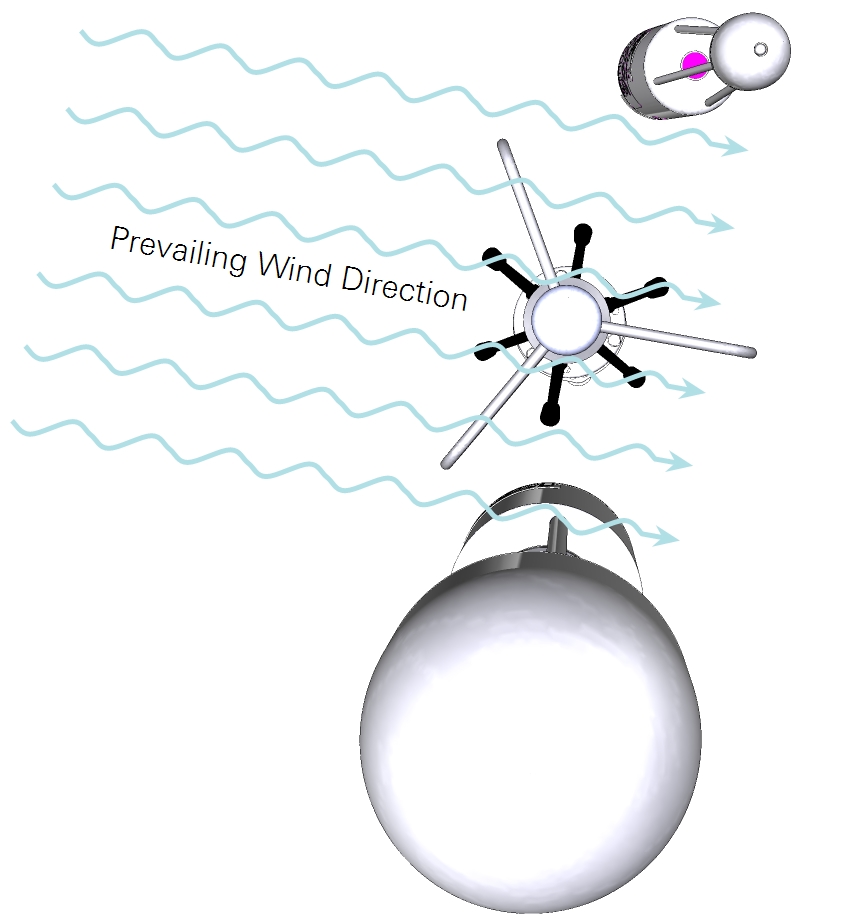
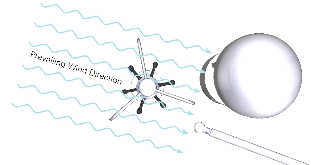
Plan your site with respect to the geographical area that is contributing to fluxes. Position the instruments so that they are both sampling the same volume of air. When using the LI-7500A/RS/DS analyzer, install the LI-7700 next to the anemometer on the opposite side of the CO2/H2O analyzer (see Figure 3‑3). When using the LI-7200/RS, install the LI-7700 near the inlet (see Figure 3‑4.
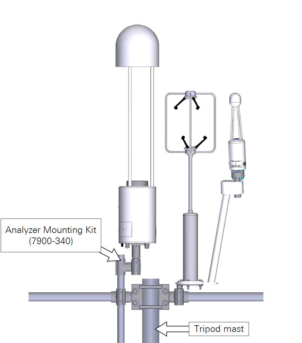
Mounting the LI-7700 on a cross arm
The LI-7700 mounting post is designed to fit securely into a 1” crossover fitting. Install it with a vertical orientation. For height adjustments, use the mounting kit (7900-340), which includes crossover fitting, riser bar, and swivel mount. Tighten all set pins in the crossover fittings tightly to prevent the instrument from shifting on the cross arm.
Set screws should be tightened to 22 N•m (16 ft•lbs). If no torque wrench is available, tighten each set screw until it contacts the pipe, then one more full revolution for aluminum pipe, or ¼ revolution for stainless steel. Use a 5/32" hex key for all the fittings except the ¾" × 1" crossover fitting (7900-342), which uses a 3/16" hex key.
Attaching the spray nozzle and washer assembly
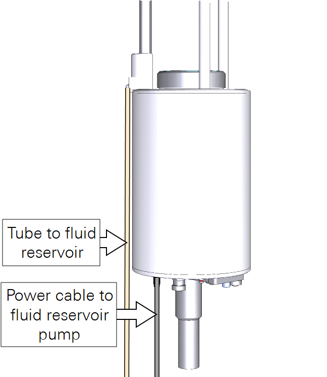
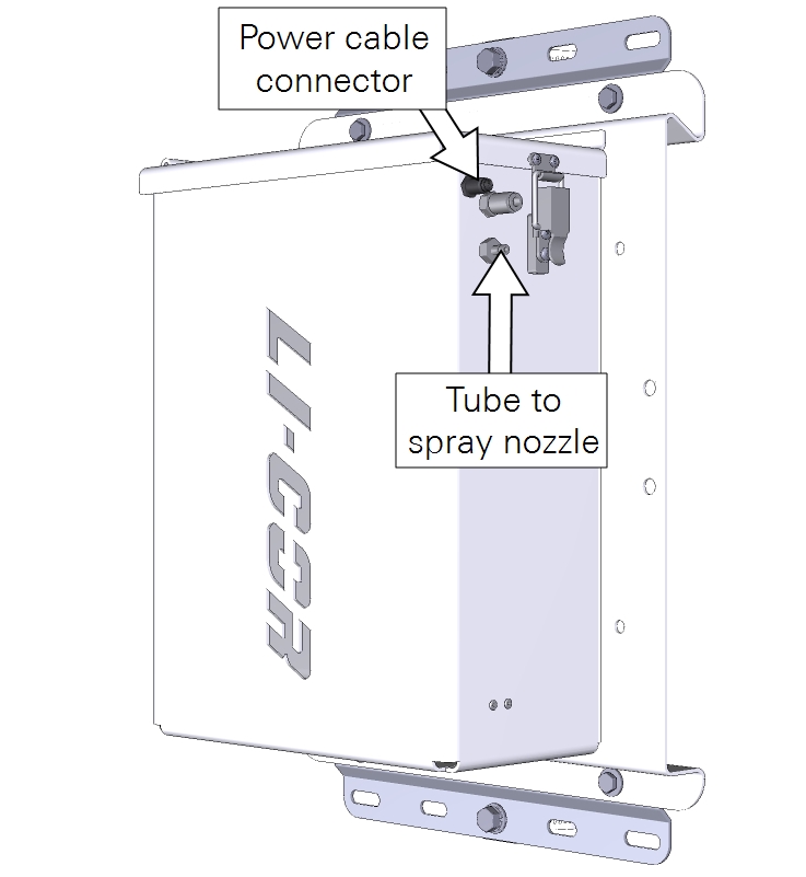
The spray nozzle assembly attaches to a spar on the LI-7700. It has two parts that fit together. Attach the hose to the washer reservoir (part number 7700-101). Connect the washer motor power cable (part number 392-10211) . It goes between the washer power connection on the LI-7700 connection panel and to the connection on the washer reservoir. Fill the washer with regular automotive windshield washer fluid or an environmentally friendly alternative. If there is risk of freezing temperatures, select a washer fluid that will not freeze.
To verify the washer operation, click Manual Controls and set the Control Setting to On and click Apply. After observing the spin motor (the pump will not run), set the Control Setting of Off and click Apply.
Note: While you may use the On setting to spin the mirror, the fluid pump will not power up. It is controlled exclusively by the time scheduling algorithm.
Mounting the washer reservoir
Mount the 7700-101 Washer Reservoir to a tripod or other post using mounting kit. Alternatively, the four holes in the corners of the box can be used to attach the box directly to a flat surface.
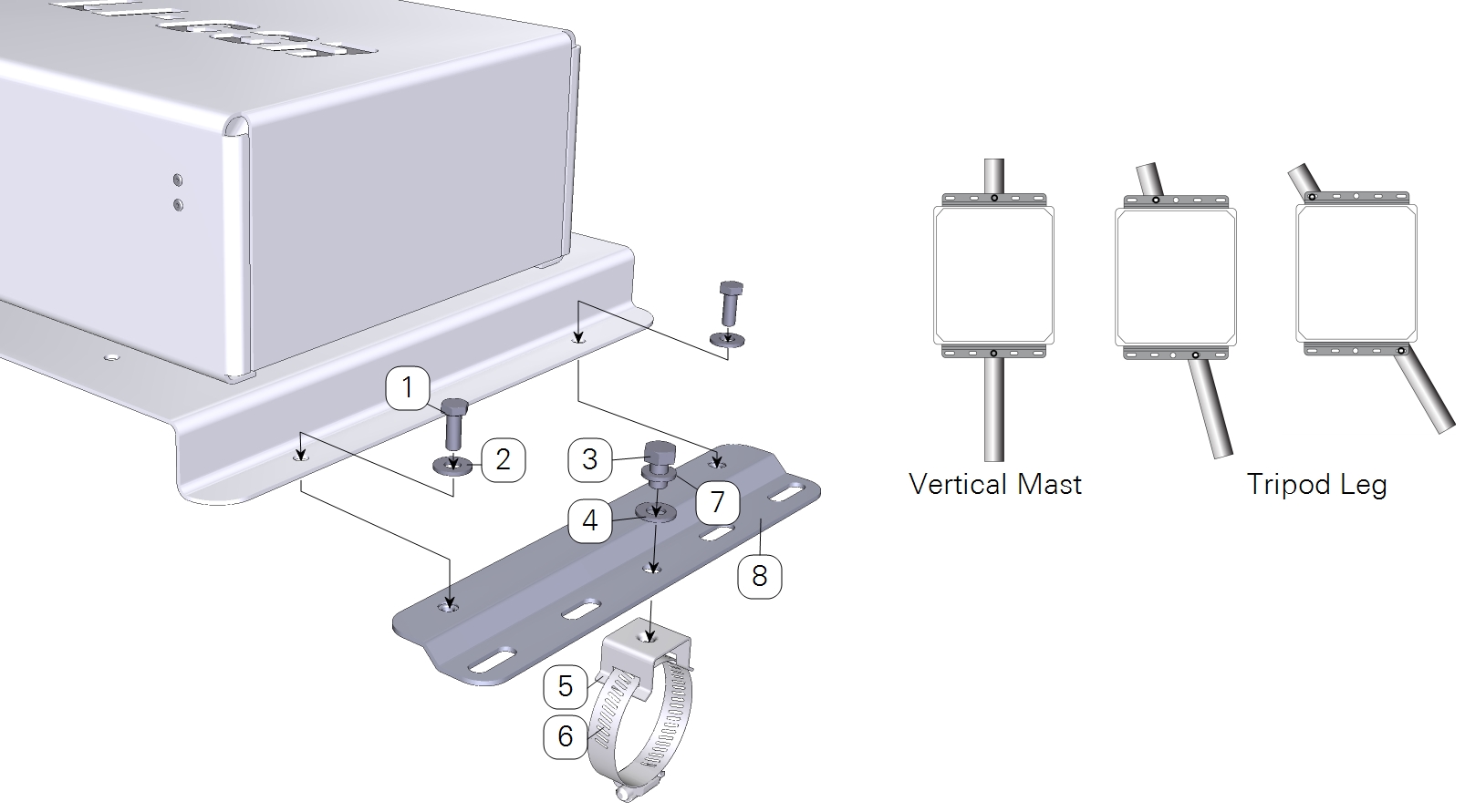
| Item | Qty. | Part Number | Description |
|---|---|---|---|
| 1 | 4 | 150-12943 | Hex Head Bolt M6x1 × 16 mm |
| 2 | 4 | 167-02054 | Flat Washer 1/4 x 5/8” |
| 3 | 2 | included w/ item #4 | Hex Head Bolt 5/16-24 × 1/2” |
| 4 | 2 | included w/ item #4 | Flat Washer 5/16” |
| 5 | 2 | 235-13234 | Flared-Leg Mounting Bracket |
| 6 | 2 | 300-13293 | Band Clamp 9/16” |
| 7 | 2 | 167-05635 | Split Washer 5/16” |
| 8 | 2 | 9879-045 | Mounting Plate |
The cable and hose assembly is 5 meters long. The washer reservoir must be within 5 meters of the LI-7700. The pump is powerful enough to lift the washer fluid 5 meters, but attempts to lengthen the washer hose will result in reduced fluid pressure, which will affect the performance of the pump and mirror cleaner. An additional reservoir can be used with the LI-7700. This might be necessary in circumstances in which the washer fluid may be used quickly.
Collect data on the gas analyzer position
The final step of the site setup is to measure a number of parameters at the site. Each of the following should be recorded for later entry into the software. These values are used in flux calculations.
Some of the required information is described in the LI-7500A/RS/DS or LI-7200/RS instruction manual. Here we describe the parameters relevant to the LI-7700.
Measure the north, east, and vertical offsets.
- Northward Separation (cm): North (positive) or south (negative) distance between the anemometer and LI-7700 sample volume midpoint.
- Eastward Separation (cm): East (positive) or west (negative) distance between the anemometer and LI-7700 sample volume midpoint.
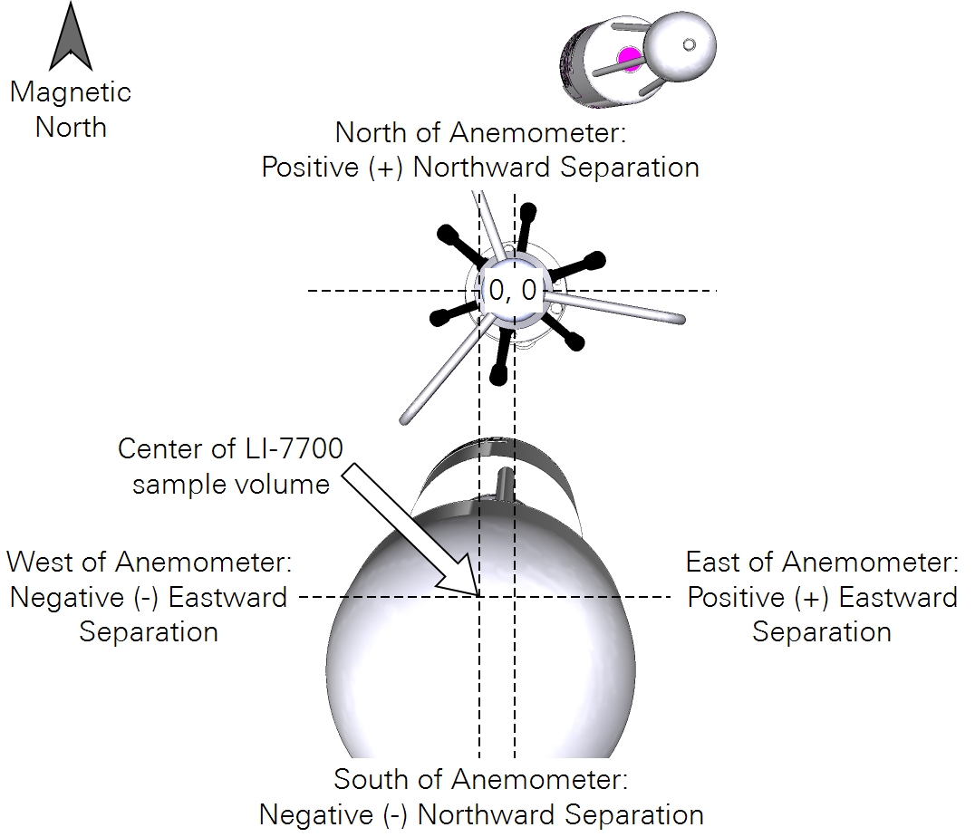
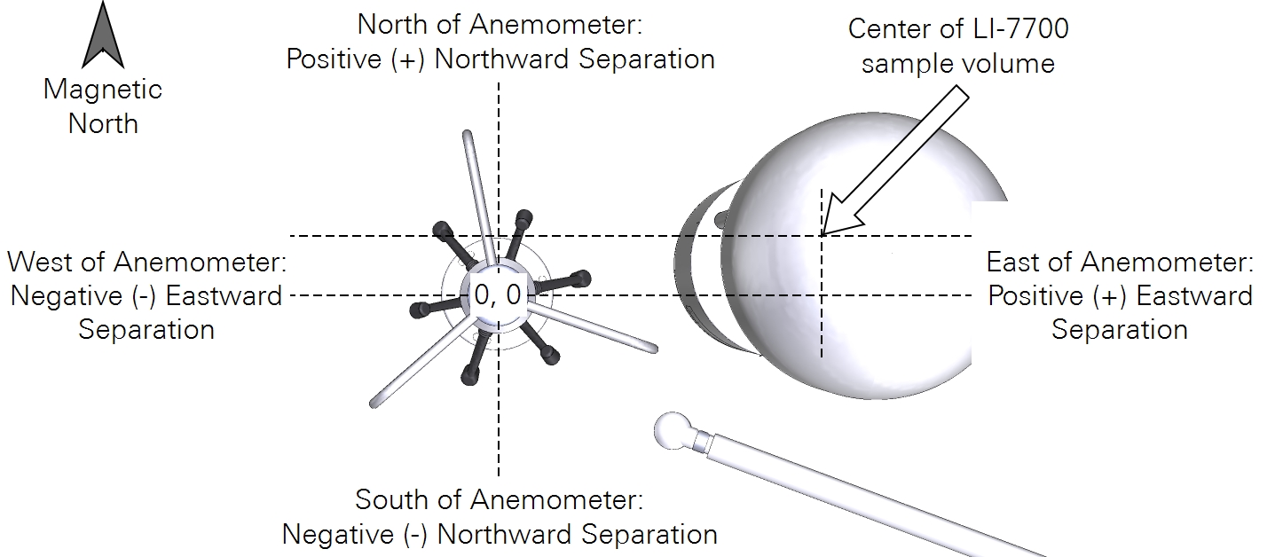
- Vertical Separation (cm): Distance between the anemometer midline and the LI-7700 sample midline. Positive value if the midline is above the anemometer midline; negative value if the midline is below the anemometer midline.