
LI-8100/A Source and Detector Replacement
Printable PDF: LI-8100/A Source and Detector Replacement
(8x0-and-8100-Source-and-Detector-InstallGuide_17308)
Download this content as a pdf that can be saved to your computer or printed.
The LI-8100A Soil Gas Flux System the source and detector on this optical bench can be replaced if they fail. These instructions describe how to change the source, detector and/or optical bench. A Phillips head screwdriver and a 1/2” open end wrench are the only tools needed to replace the source and/or detector in all instruments. To replace the source or detector:
| Component | Part Number |
|---|---|
| Source | 8100-902 |
| Detector | 800-906 |
| Optical Bench | 800-904 |
Note: Be sure that you are properly grounded to avoid electrostatic discharge that can damage the electronics. Use an anti-static wrist strap, electrostatic discharge grounding mat, or occasionally touch bare metal that has a clear path to ground, such as an unpainted computer case.
- Power the instrument off and remove the battery or other external power source.
- Allow the instrument optical bench to cool for about 10 minutes.
- Open the Analyzer Control Unit and remove the access panel by loosening the 4 thumbscrews.
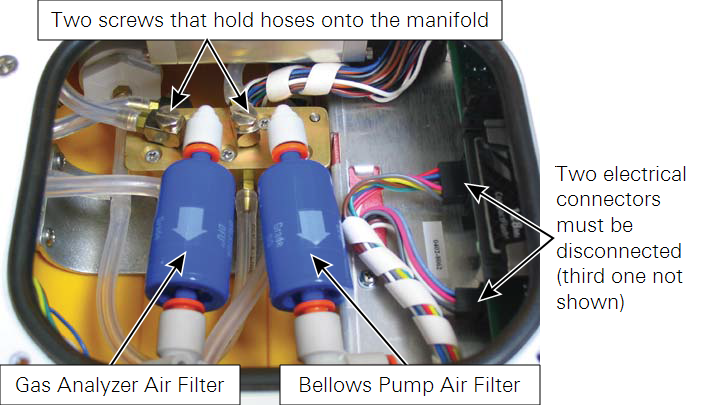
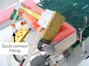
- Remove both air filters by pressing the orange part of the quick-connect fittings toward the white part of the connector and pulling the filter out.
- Discard the filters. There are replacement filters included that can be used during reassembly.
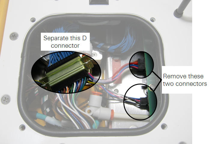
- Disconnect the 3 electrical connectors.
- Two of them are on a single wiring harness, just to the right of filter connectors; the third is at the left end of the bundle of blue cables. Pull straight out on the connectors to remove them.
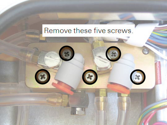
- Remove the 5 screws from the top of the air manifold.
- The top half of the manifold rests on two pins; lift the top half until it is completely separated from the bottom half. It is not necessary to remove any of the hoses.
- Remove the 12 screws around the outer edge of the white panel.
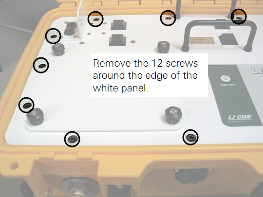
- Lift the assembly out of the yellow case and turn it upside down.
- Remove the 6 screws from the optical bench cover.
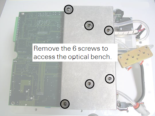
- Leaving the hoses connected to the optical bench, lift the bench out of the foam casing.

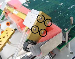
- There are four screws on the source and detector housings that must be removed.
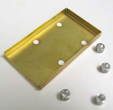
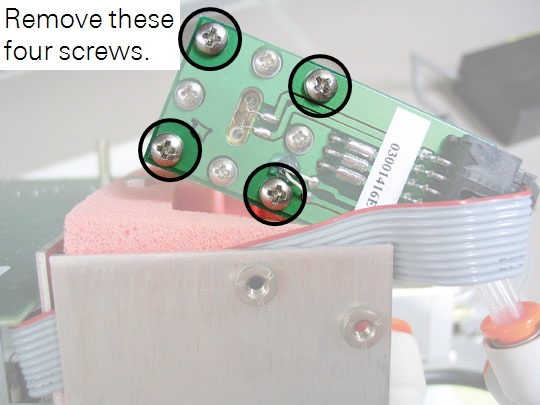
- Remove only the screws from the assembly you are replacing. Remove the four screws in the corners of the source housing circuit board. Do not remove the remaining four screws. Remove the four screws from the detector housing cover. Note that there are some small standoffs inserted over the screws behind the cover; tilt the housing down when removing the cover so these standoffs don’t get lost.
- Disconnect the ribbon cable connectors attached to the source and/or detector housing circuit board.
- Remove the Bev-A-Line® tubing connected to the source and/ or detector housing at the quick-connect fitting.
- Press down on the orange part of the fitting to remove the tubing.
- The source and/or detector housing, with the attached circuit board and tubing can now be removed and discarded.
- Note that there are O-rings on each end of the optical bench. It is a good practice to replace the O-ring when replacing the source. Make sure the optical path tube is clean (no dust, dirt, etc.) before proceeding. Clean it if needed, as described in the instruction manual.
- Re-assemble the bench using the replacement source and/or detector.
- Be sure the O-rings are in place on both ends of the bench. Note that the orientation of the optical bench cylinder is not important; either end can be inserted into the source or detector housing.
- Replace the tubing.
- Any tubing that you removed should be replaced with a piece of equal length, which can be cut from the tubing that is included in the instrument spares kit.
- Re-assemble the LI-8100A case.
- Make sure that the foam insulation on the inside top cover is positioned over the optical bench; it is required for thermal stability. The remaining assembly procedures are the opposite of the disassembly.
- Perform zero and span calibrations as described in the LI-8100A Instruction Manual.
- A simple zero and span will be adequate if the span gas is close to the concentrations you will measure. A dual span, however, will bring the instrument performance within specifications across the full measurement range. If you do not have zero and span gases, send the instrument back to LI-COR for a factory recalibration.