
Printable PDF: Long-Term Chamber Thermistor Upgrade or Replacement Instructions
(8100_InstallGuide_Thermistor_Replacement_ACU105.pdf)
Instructions for replacing the long-term chamber thermistor.
The 8100-908 is a replacement/upgrade for the thermistor assembly in the 8100-101 Long-Term Chamber. The 8100-908 can be field installed; the upgrade requires approximately 15-20 minutes to complete.
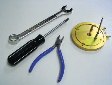
Tools required: Philips head screwdriver, 11/16” open end wrench, and a knife or pair of cutters.
Follow these steps to replace the thermistor assembly:
- Manually open the chamber, using the Manual Controls function in software, until it reaches a vertical position at the apex of its movement. This will allow you to remove the white chamber “bowl” in a later step.
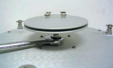
- Remove the pressure vent from the top of the chamber. In many cases you can simply twist the vent assembly counterclockwise with your hands to remove; if not, use the 11/16” open end wrench to loosen the nut at the base of the vent assembly.
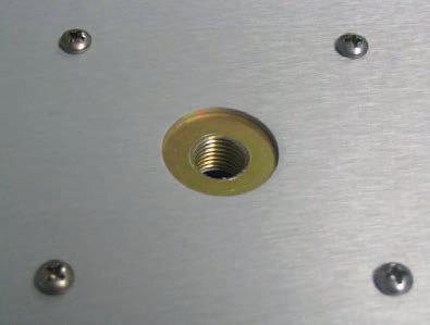
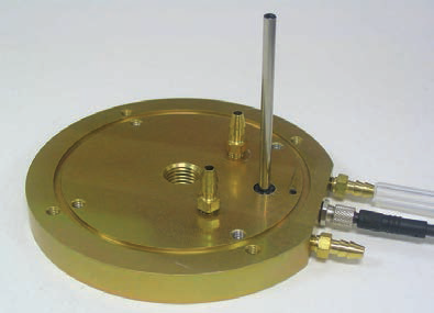
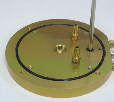
- Remove the 4 screws from the top mounting plate assembly, underneath the pressure vent.
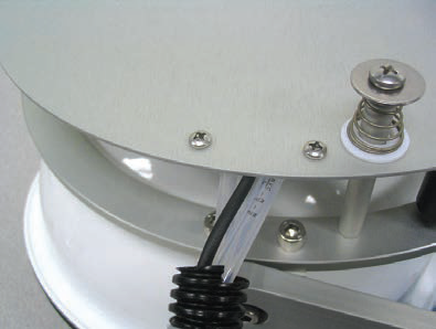
- Remove the 2 screws at the edge of the top mounting plate assembly that secure the air tubing assembly.
- The chamber “bowl” can now be moved away from the top plate assembly to access the old spacer/thermistor assembly.
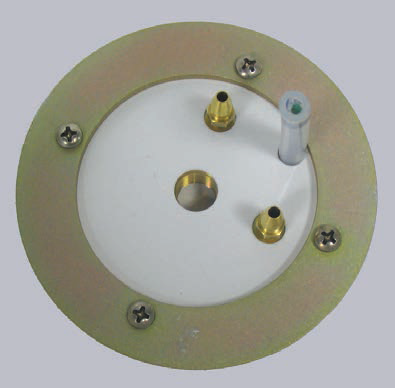
- Remove the 4 screws from the underside of the chamber “bowl”, and remove the attached mounting plate. The old spacer/thermistor assembly can now be moved away from the top of the chamber “bowl”.
- Cut the air tubing off as close to the hose barbs as possible. Unscrew the collar from the thermistor cable between the two hose barbs. Discard the old spacer/thermistor assembly.
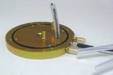
- Insert the air tubing over the two hose barbs on the 8100-908; it does not matter which tube is attached to either barb. Reattach the thermistor cable collar.
- Make sure the O-ring is in place in the new 8100-908 assembly. Insert the assembly through the holes in the top of the chamber “bowl”. Replace the mounting plate removed in Step 5 above and secure with 4 screws.
- Move the chamber “bowl” back under the top mounting plate assembly, and align the holes in the 8100-908 assembly with the 4 screw holes in the top mounting plate assembly. Replace the 4 screws on the top mounting plate that were removed in Step 3 above.
- Reattach the air tubing assembly at the edge of the top mounting plate assembly.
- Make sure the O-ring is in place in the nut at the base of the pressure vent support tube. Reattach the pressure vent assembly. The assembly is complete.