
Printable PDF: 8150-916 Eight-to-Sixteen Port Upgrade Kit for the LI-8150 Multiplexer
(8100_InstallGuide_8150_Sixteen_Port_Upgrade_ACU106.pdf)
Instructions for the eight-to-sixteen port upgrade kit.
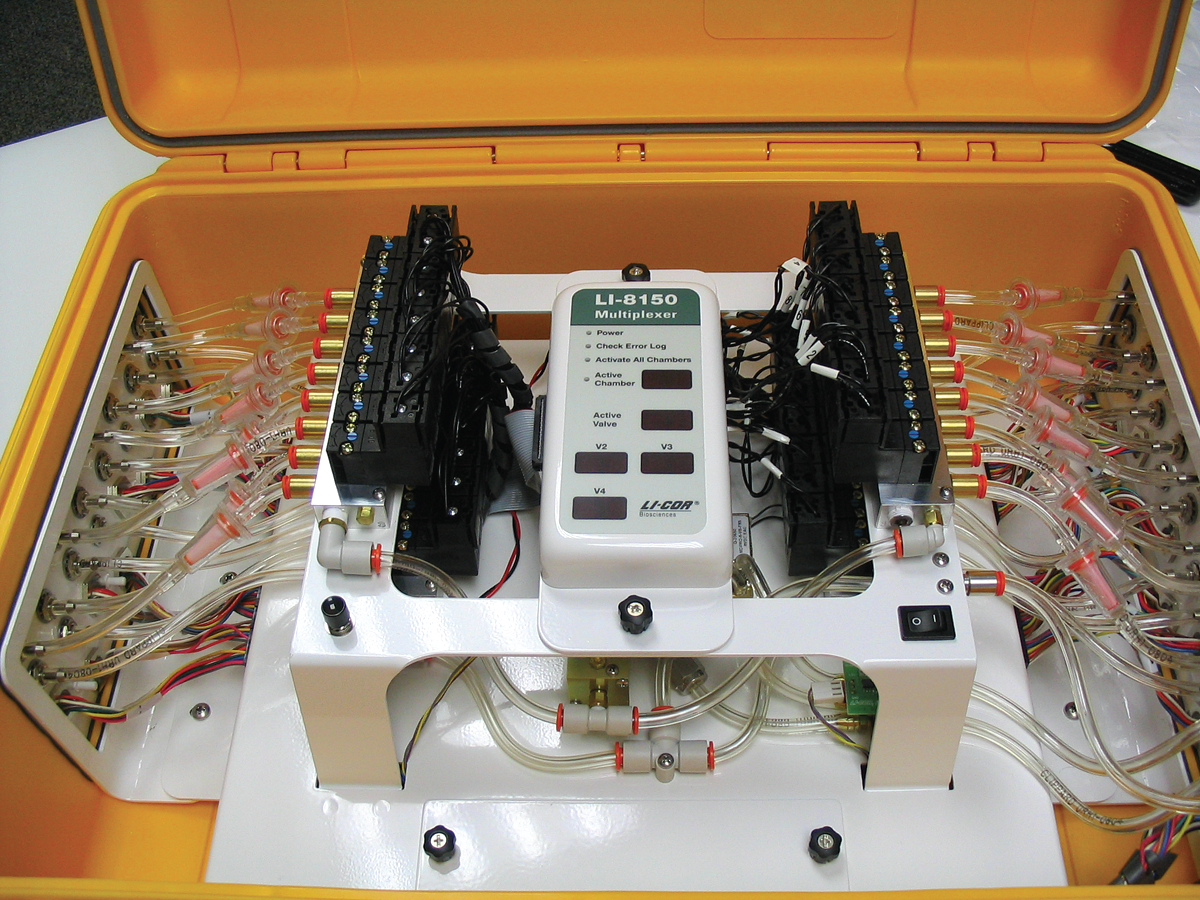
The LI-8150 Multiplexer is configured at the factory with either 8 or 16 ports; the 8 port multiplexer can be upgraded in the field with the 8150-916 Upgrade Kit. The upgrade takes approximately 45-60 minutes to complete, and requires only Philips head screwdrivers (#1 and #2) and a small pair of wire cutters, or alternatively, a sharp knife.
Follow these steps to upgrade the Multiplexer:
- Turn off the instrument and remove the power cord from the connector on the instrument side panel.
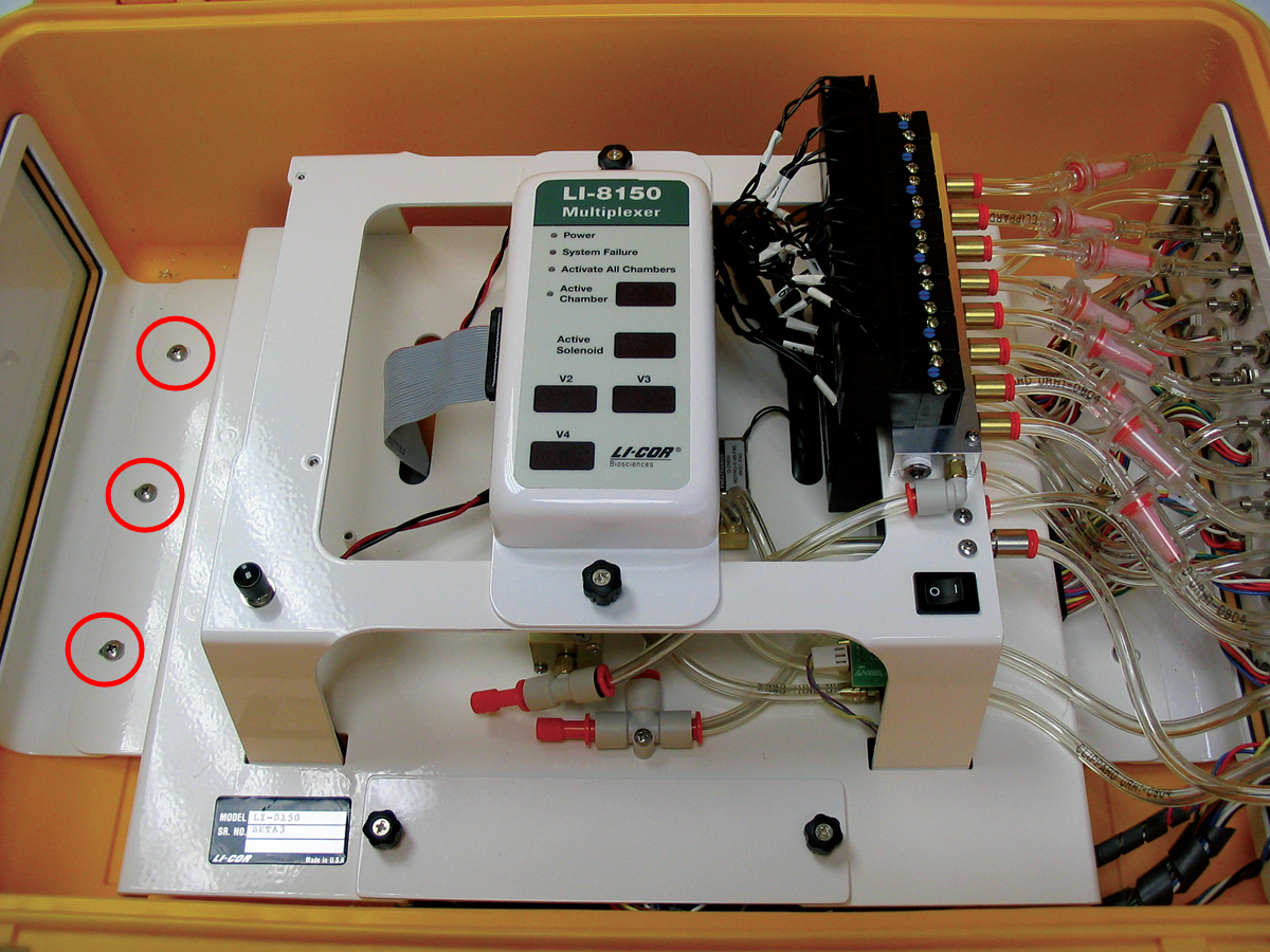
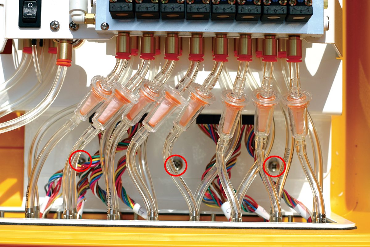
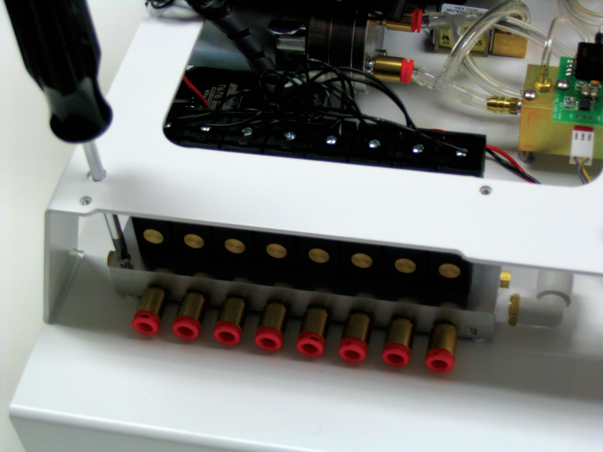
- Remove the six screws indicated in the images below; three on the left side of the main assembly, and three on the right side, under the existing tubing.
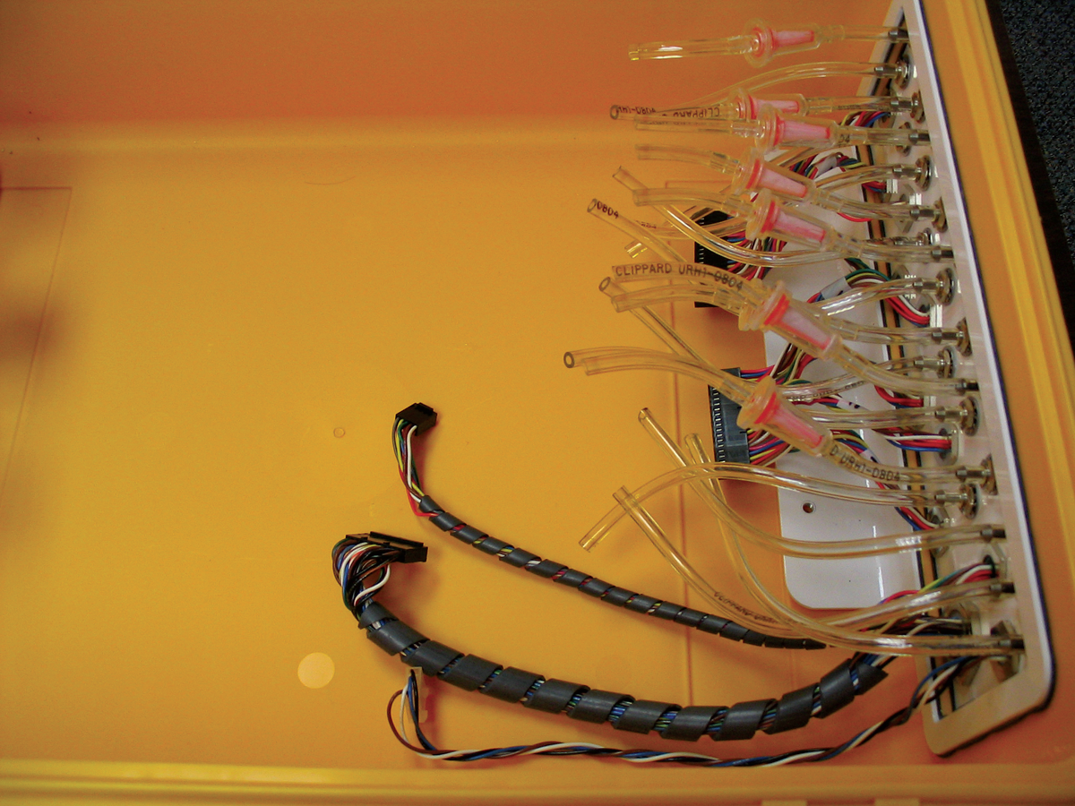
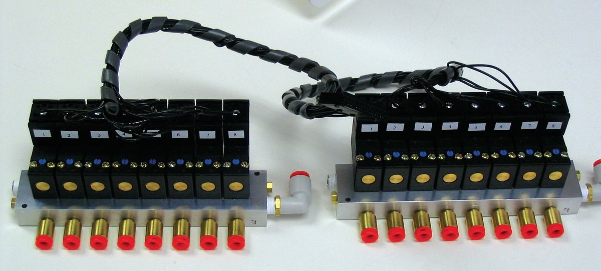
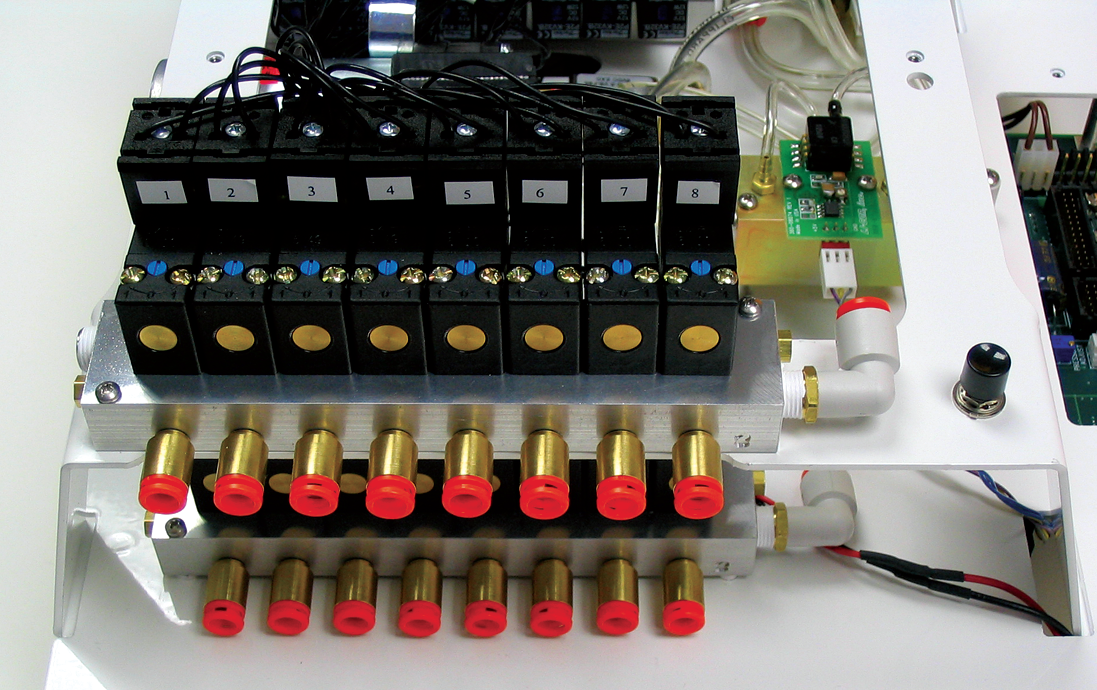
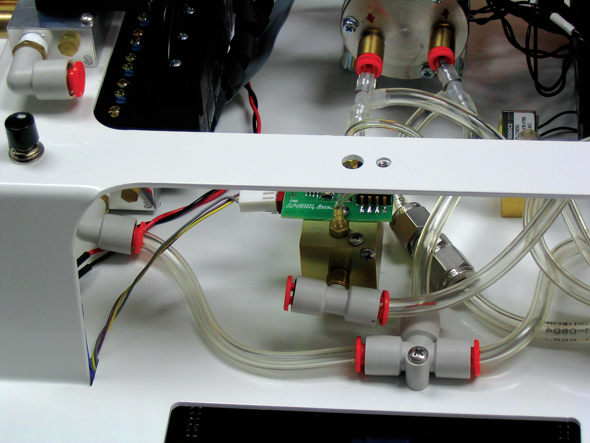
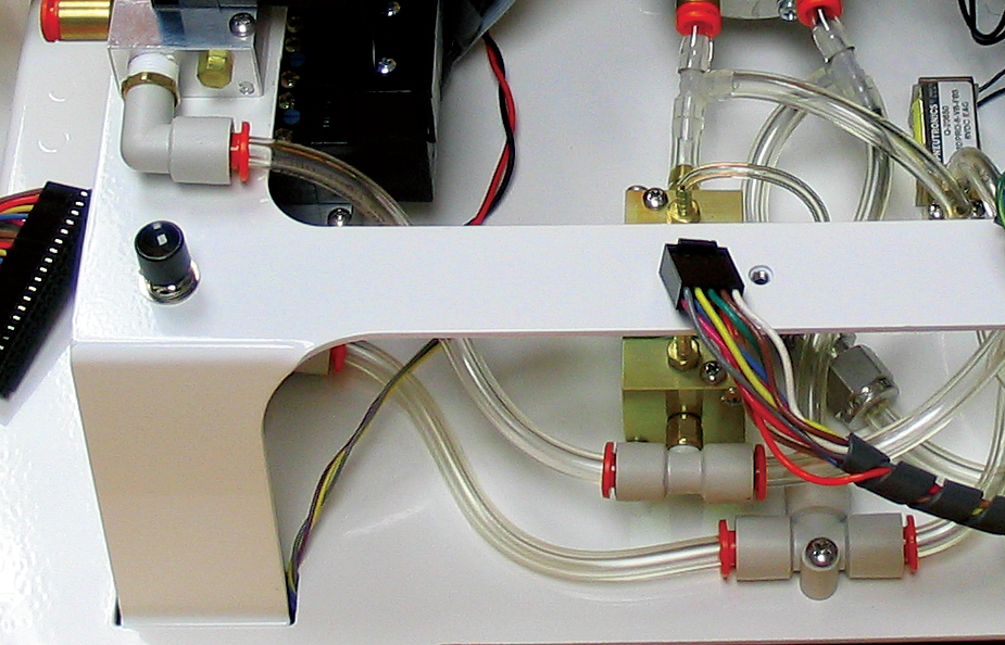
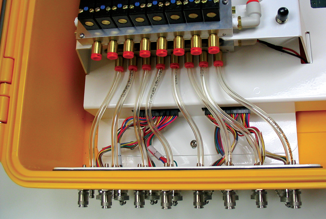
- Disconnect the existing tubing from the right control panel assembly at the compression fittings. There are connections at 19 locations; 8 each on the upper and lower solenoid valve assemblies, and 3 on the Air In (I), Air Out (O), and Pressure (P) fittings, respectively. Push in on the orange collar of the compression fittings and pull straight out on the tubing to remove.
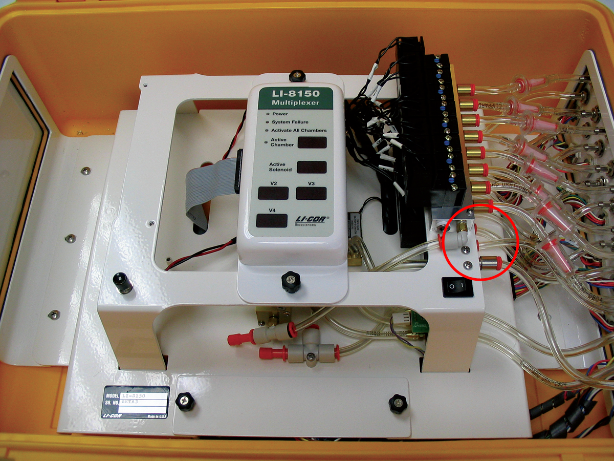
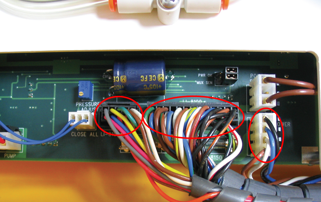
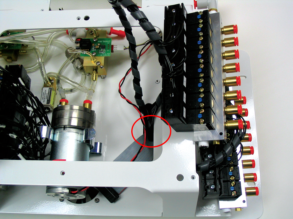
- Disconnect the two electrical connectors located under the tubing.
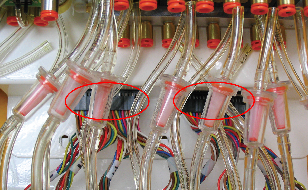
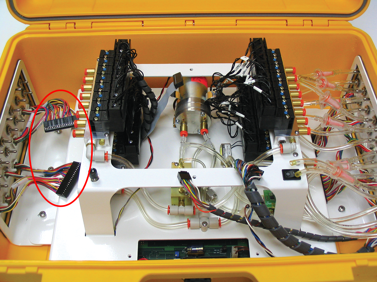
- Loosen the two thumbscrews and remove the access panel. Disconnect the three wiring connectors shown in.
- Remove the entire assembly from the box, leaving the side panel assembly, tubing, and electrical connectors.
- Remove the screws from the left panel plate cover and discard the plate. Insert the chamber control panel assembly (ports 9-16) and attach with the screws removed from the plate cover (torque to 8 in.-lb.).
- Locate the solenoid valve cable assembly (p/n 9981-113). This cable assembly has a single connector on one end; the other end is divided into the solenoid valve assemblies for the upper and lower solenoid banks. Note that one of the sets of valve assemblies is attached via a short cable, and the other set via a slightly longer cable.
- Attach either set of valves to one of the two solenoid blocks. The connectors are numbered 1-8; attach in order from left (1) to right (8). Secure each valve with the supplied screw (torque to 8 in.-lb.).
- Unplug the connector on the left side of the LED panel, and set the panel aside. Thread the single connector end of the solenoid valve cable assembly down through the slot in the main assembly lower plate; it will be attached to the underside of the assembly in a later step.
- The lower solenoid block assembly fits over four small studs on the main assembly plate; secure the block assembly with only two 4-40 x 7/8” screws (p/n 122-05791). Torque to 8 in.-lb. The left side of the block is attached near the front of the block; the screw can be tightened through the hole in the top of the main assembly top plate. The right side of the block is attached near the rear of the block.
- Thread the upper solenoid block up through the cutout in the main assembly top plate. Mount the upper solenoid bank to the main assembly top plate with two 4-40 x 7/8” screws (p/n 122-05791). Torque to 8 in.-lb.
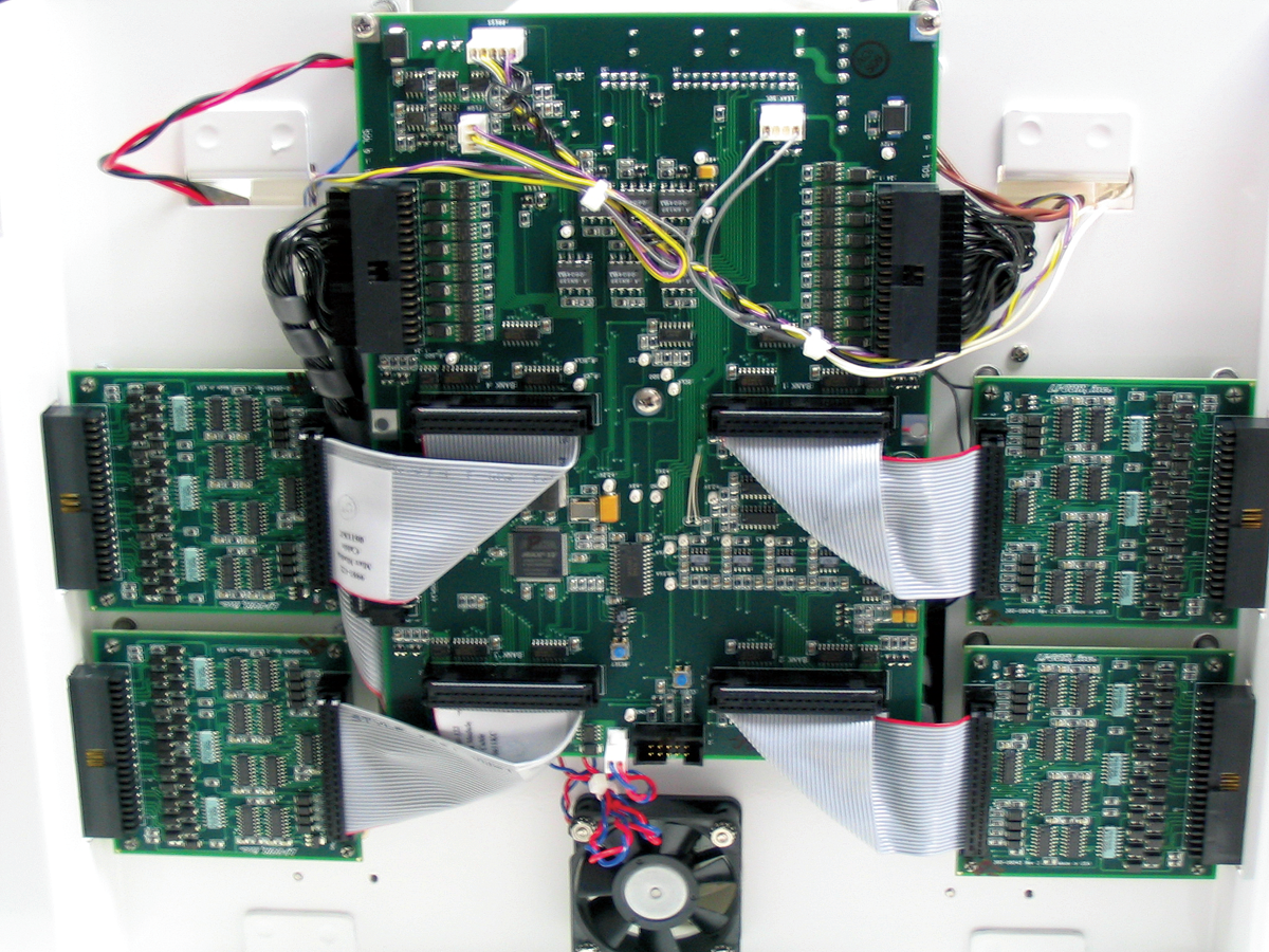
- Before installing the PCA module boards, attach the disposable static wrist strap included. Carefully invert the main assembly. Connect the solenoid valve cable assembly. Attach two of the PCA module boards. Push on the 4 corners of the boards until they snap into place.
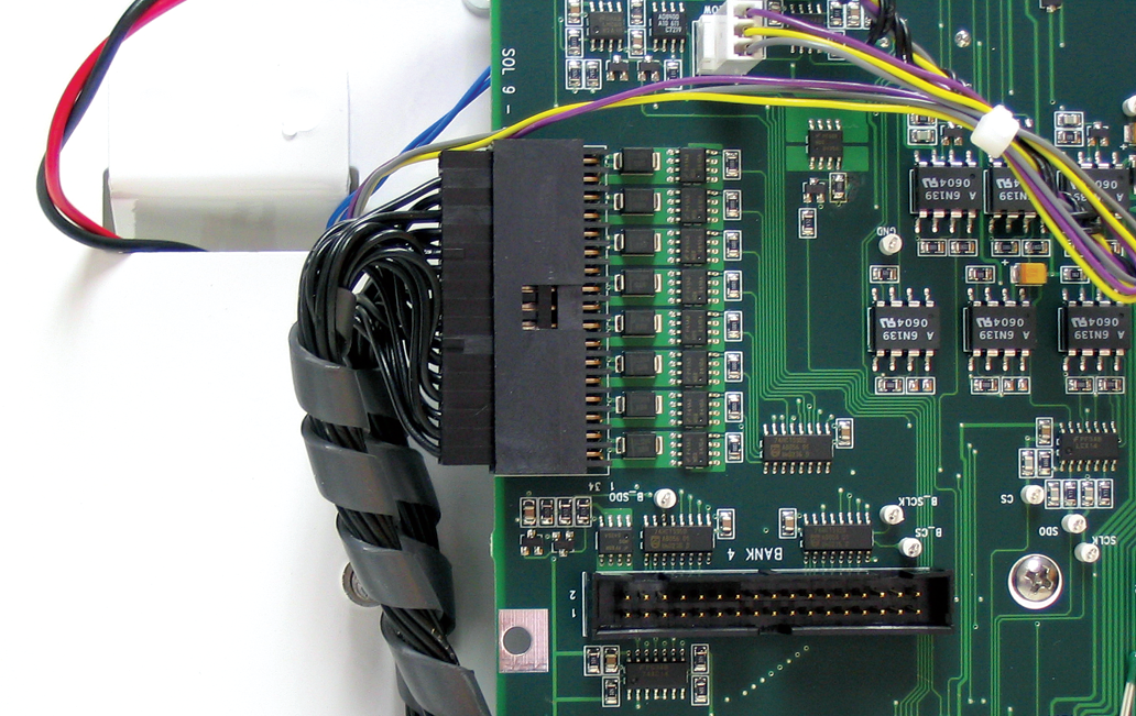
- Connect the module boards to the main board using the ribbon cables (p/n 9981-122). Note that either end of the ribbon cable can be attached to the module and main boards.
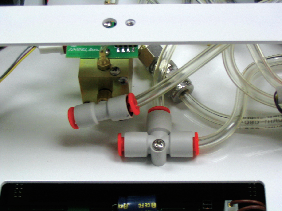
- Turn the main assembly back over and locate the two “T” fittings. Remove the plugs from the fittings and discard. Measure a length of the urethane tubing between either of the solenoid blocks and the appropriate “T” fitting shown; leave enough slack to make a slight “S” curve in the tubing. Cut the tubing to length and attach to the quick connect fittings.
- Insert the main assembly back into the multiplexer case. Start the six screws removed in Step 2, but do not tighten fully yet. Reconnect the tubing at 19 locations, and the two electrical connectors under the tubing. Reconnect the three electrical connectors under the access panel removed in Step 5. Center the main assembly, so that there is some slack in the existing tubing, and tighten the six screws (torque to 39 in.-lb.). Push and pull on the tubing to see if the connections are tight.
- Connect the two electrical connectors on the left side control panel assembly to the main board.
- Use the urethane tubing to connect the lower solenoid assembly block to the lower flow connections on the control panel assembly (Air Out). Insert the free end of the urethane tubing into the quick connect fitting(s) on the solenoid bank first, and then cut to length, so that there is a slight “S” curve in the tubing. Repeat for all eight lower flow connections.
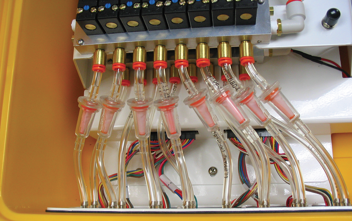
- The upper solenoid assembly block is connected to the control panel assembly with the included filter assemblies (p/n 9981-123). Note the orientation of the filters; there is an arrow embossed on the filter, which must point toward the solenoids. The filter assemblies are cut to a standard length; some may need to be trimmed slightly so that they each have a slight “S” curve. Attach all eight filter assemblies, making sure the tubing isn’t crimped.
- Perform a leak test on the system as described in the LI-8100 Instruction Manual.