
Printable PDF: Installing the 8100-203 Soil Temperature Thermistor Probe
(8100A_Soil-Temperature-Probe_20799.pdf)
Instructions for using the soil temperature thermistor.
The 8100-203 Soil Temperature Thermistor Probe kit consists of a Soil Temperature Thermistor Probe (p/n 8150-203) and a Probe Adapter (part number 9981-150) that mates to the Soil Temperature Thermistor Probe; the Probe Adapter contains a resistor that allows the 8150-203 Soil Temperature Thermistor Probe to be used with the Auxiliary Sensor Interface on the LI-8100 Automated Soil CO2 Flux System.
Follow these steps to install the Probe Adapter onto the Auxiliary Sensor Interface, and subsequently, attach the 8150-203 Soil Temperature Thermistor Probe:
- Loosen the 4 Philips head screws in each corner of the Auxiliary Sensor Interface module and remove the top cover.
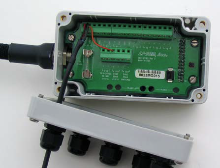
- There are 5 strain relief “gland” type plugs on the Auxiliary Sensor Interface top cover, through which the sensor wires pass, after which the wires are connected to the appropriate screw terminals. Remove the cap from any of the 5 gland plugs by turning counterclockwise.
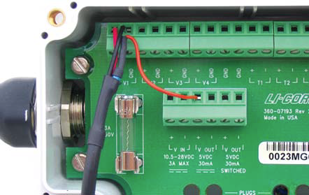
- Pass the 3 wires on the end of the Probe Adapter through the top of the plug cap, and then through the gland plug. Screw the plug cap slightly, but don’t tighten yet.
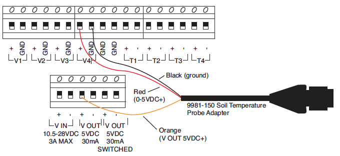
- Use a small flathead screwdriver to loosen the appropriate screw terminals, and insert the wire leads into the terminal strip. Tighten the screw terminals. Make a note of which plug the wires are passing through (A, B, C, D or E), and to which terminal the wires are connected (e.g. A/V1, B/V2, etc.). This information will be needed later when you enter the calibration coefficients for the soil temperature probe into software.
- Pull lightly on the wires to remove excess wire from inside the interface, re-attach the interface top cover, and tighten the gland plug cap. Tighten the screws on the interface top cover. Mate the 8150-203 Soil Temperature Probe and 9981-150 Soil Temperature Probe Adapter ends.
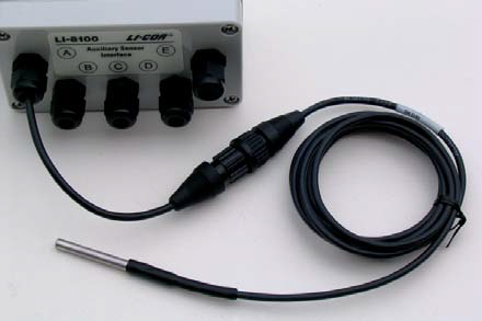
- Attach the Auxiliary Sensor Interface cable connector to the connector on the side panel of the LI-8100 Analyzer Control Unit labeled “Aux. Sensor Interface”. Attach the Auxiliary Sensor Interface to the Analyzer Control Unit using the metal fittings provided, if desired.