Printable PDF: Installation Instructions for the ThetaProbe Soil Moisture Sensor
(8100-204_Theta_Probe_InstallGuide_ACU112.pdf)
Instructions for using the ML2x ThetaProbe.
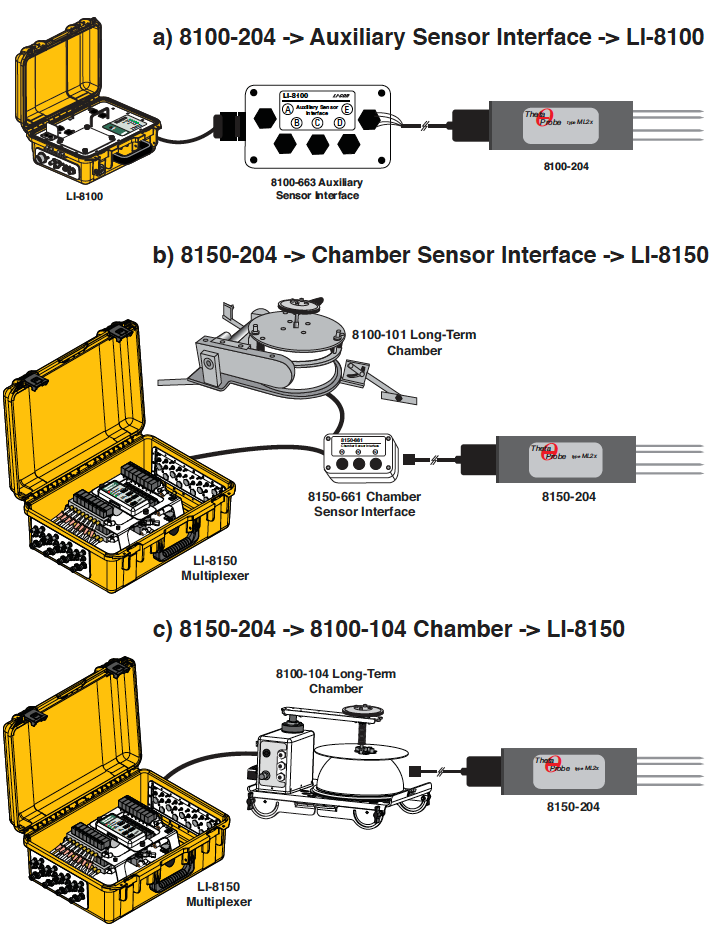
The 8100-204 and 8150-204 Soil Moisture Probes (Delta- T Devices Ltd., Cambridge, England) are now available for use with the LI-8100 Automated Soil CO2 Flux System. The ThetaProbe is offered as an alternative to previous soil moisture probes. The 8100-204 and 8150- 204 differ only in the way the cable is terminated; the 8100-204 has bare wire leads, and is for use only with the LI-8100 Auxiliary Sensor Interface. The 8150-204 has a connector pre-installed for direct connection to the 8100-104 soil chamber, or the Chamber Sensor Interface (part number 8150-661) when used with the LI-8150 Multiplexer (see Typical Soil Probe Connections). The following instructions describe how to connect the 8100-204 to the Auxiliary Sensor Interface; if you are using the 8150-204, skip directly to Step 8 on the next page.
Follow these steps to install the 8100-204 onto the Auxiliary Sensor Interface:
- Loosen the 4 Philips-head screws in each corner of the Auxiliary Sensor Interface module and remove the top cover.
- There are 5 strain relief “gland” type plugs on the Auxiliary Sensor Interface top cover, through which the sensor wires pass, after which the wires are connected to the appropriate screw terminals. Remove the cap from any of the 5 gland plugs by turning counterclockwise.
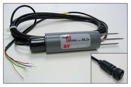
- There are 5 wires on the end of the 8100-204 cable; only 4 of these wires are used with the Auxiliary Sensor Interface. The bare copper braided wire can be clipped off, or connected to an earth ground if one is available. The 8150-204 has a connector (inset).
- Pass the 4 wires from the 8100-204 through the top of the plug cap, and then through the gland plug. Screw the plug cap slightly, but don’t tighten yet.
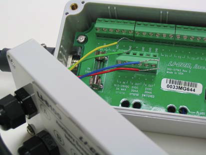
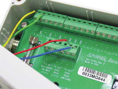
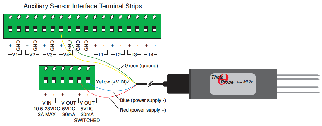
- Use a small flathead screwdriver to loosen the appropriate screw terminals, and insert the wire leads into the terminal strip. Tighten the screw terminals. Make a note of which plug the wires are passing through (A, B, C, D or E), and to which terminal the wires are connected (e.g. A/V1, B/V2, etc.). This information will be needed later when you enter the calibration coefficients for the soil moisture probe into software.
- Pull lightly on the wires to remove excess wire from inside the interface, re-attach the interface top cover, and tighten the gland plug cap. Tighten the screws on the interface top cover.
- Attach the Auxiliary Sensor Interface cable connector to the connector on the side panel of the LI-8100 Analyzer Control Unit labeled “Aux. Sensor Interface”. Attach the Auxiliary Sensor Interface to the Analyzer Control Unit using the metal fittings provided, if desired.
- Slope and offset coefficients for linear input devices need to be entered into the Windows Application Software or mobile app before using the soil probe.
-
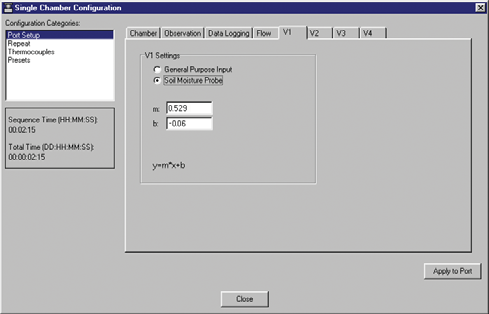
The 8100-204 and 8150-204 use different linearization coefficients, based on the organic content of the soils into which the probe is inserted. In general, if the soil is classified as a Mineral soil, with < 7% organic content, the probe uses one set of coefficients, and if the soil is classified as an Organic soil, with > 7% organic content, the probe uses a second set of coefficients, as follow:
| Soil Type | Organic Content | Bulk Density (g cm-3) | Use for bulk density (g cm-3) | Slope | Offset |
|---|---|---|---|---|---|
| Mineral | <7% | 1.25 to 1.5 | >1.0 | 0.529 | -0.060 |
| Organic | >7% | .2 to 0.7 | <1.0 | 0.577 | -0.026 |
It is possible to perform soil-specific calibration of the soil moisture probe to obtain linearization coefficients; refer to the ThetaProbe ML2x instruction manual for more information.
Typical Soil Probe Connections