
Measurement of CO2 Evolution in a Multiplexed Flask System
1 | Introduction
2 | Flask Volume, Mixing and Flow Considerations
2.1 | Volume
The LI-8100A operates as a closed system, determining CO2 flux from the change in CO2 mole fraction over time in a fixed volume. In its simplest form (ignoring dilution due to water vapor and not standardizing the rate for sample area or mass) the relationship between carbon flux and the change in CO2 mole fraction with time takes the following form
1

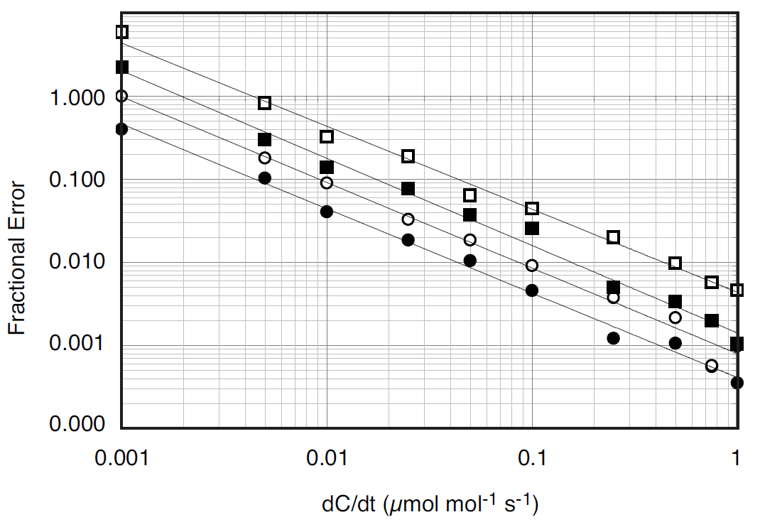
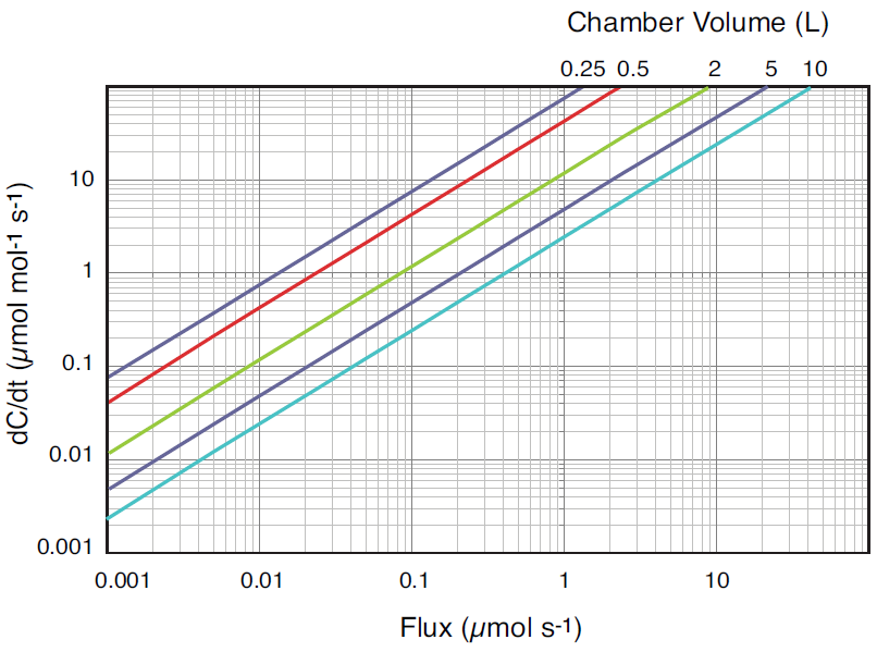
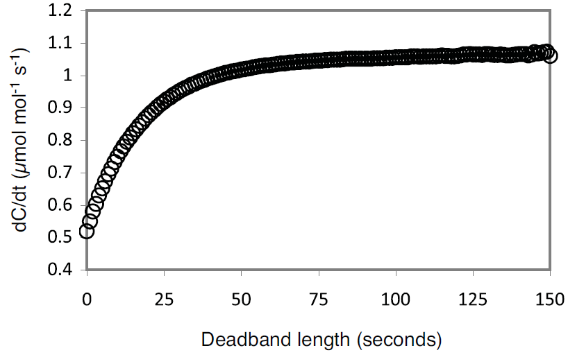
where F is the flux in μmol s-1, P is pressure in kPa, V is the system volume in liters, R is the ideal gas constant, T is temperature in K, and dC/dt is the change in CO2 mole fraction with time (μmol mol-1 s-1). At ambient pressure, system volume is the single largest factor controlling the relationship between dC/dt and flux. Given the same flux, changing the gas temperature from 20 to 40 °C will only change dC/dt by about 7%, while doubling the system volume will cut dC/dt nearly in half because the increased volume serves to dilute the change in CO2 mole fraction within the system. As dC/dt decreases, the potential for error in the measurement due to instrument noise increases. For the LI-8100A this noise is known and its effects have been modeled over a range of dC/dt for various sampling periods (Figure 1).
A chamber volume should be chosen that over the range of expected fluxes, ensures dC/dt is large enough to be outside the influence of instrument noise. In circumstances where there are constraints on chamber size, the observation length used by the LI-8100A can be adjusted to improve the estimate of dC/dt, as increasing the number of data points used in the calculation will decrease the effect of noise (Figure 1).
2.2 | Mixing
It is important that the volume of air inside the chamber be well mixed to ensure that fluxes are calculated using representative samples of the chamber CO2 mole fraction. If there are pockets of unmixed air inside the chamber, these can act as sources or sinks for CO2 and cause errors in the flux measurement. For chamber volumes less than about four liters the pump inside the LI-8150 may provide adequate mixing. However, this is contingent on the geometry of both the chamber and the sample, and how the sample is positioned within the chamber. If additional mixing is required, small fans or baffles can be installed inside the chamber
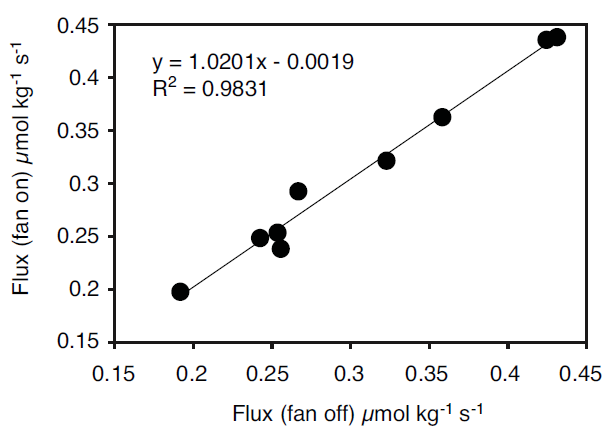
It is possible to determine if there is adequate mixing inside a chamber by looking at the relationship between fluxes measured under normal operating conditions and fluxes measured where mixing is known to be good. In the example shown in Figure 3 we measured respiration from navel oranges using a four liter chamber attached to the LI-6200 Portable Photosynthesis System. Measurements were made in pairs on the same fruit, with either mixing due only to the pump inside the LI-6200 or with additional mixing using two fans installed in the chamber. There is little difference in the measured fluxes with either the fans on or off, indicating that the chamber volume is sufficiently mixed using only the LI-6200 pump.
2.3 | Flow and chamber conditions between measurements
When configured as a multiplexed flask system, a plumbing change inside the LI-8150 allows flasks to be continuously flushed with ambient air between sampling periods. This serves as the mechanism by which CO2 and water vapor are exported from the system between measurements, preventing condensation and excessively high CO2 mole fractions from developing in the flask. The flushing rate is determined by the flow rate, provided by an auxiliary pump, and the flask volume. The time required to reduce the flask concentration by 63% (i.e., 1/e) is given by
2τ = V/f
where τ is the time constant in seconds, V is the chamber volume in liters, and f is the flow rate through the chamber in l s-1. For applications where condensation inside the chamber is unlikely, and the chamber CO2 (or other gas species; ethylene for example is known to influence respiration rates of fruit) mole fraction has little or no affect on the processes driving the flux, this is of little importance; however, the time constant is much more important in situations where condensation may occur, or when other gases present in the flask might influence the CO2 flux.
In these situations it may be useful to model the in-chamber mole fraction of the offending gas species to determine a flow rate appropriate to keep the mole fraction below problem levels. Where increasing the flow rate is not feasible, chemically scrubbing the gas species from the incoming gas stream may be necessary. Ignoring the influence of other gas species, under well mixed and steady state conditions, the chamber mole fraction for a particular gas species is controlled by the flux of that species from the sample and the flow rate through the flask, as given by
3C0 = F / f + Ci
where C0 is the in-chamber mole fraction of the gas species in μmol mol-1, F is the flux of the species in μmol s-1, f is the flow rate through the flask in μmol s-1, and Ci is the incoming mole fraction in μmol mol-1. When the flux is positive (net efflux from the sample), increasing the flow rate (decreasing τ) or decreasing the incoming CO2 mole fraction will decrease the mole fraction of CO2 in the chamber. Configuring the LI-8150 and LI-8100A for multiplexed flask measurements. These instructions describe the changes that are required in order to adapt a sixteen port multiplexer for flask measurements. The procedure for modifying an eight port multiplexer is very similar, and where significant differences exist, they have been noted. A list of parts available from LI-COR necessary for these modifications is included in Table 2.
2.4 | Plumbing
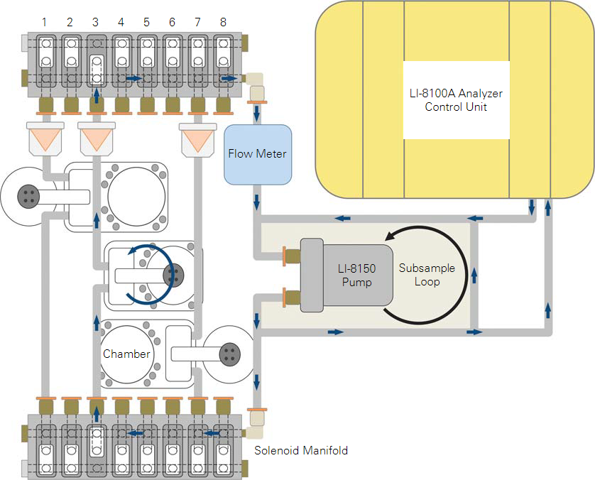
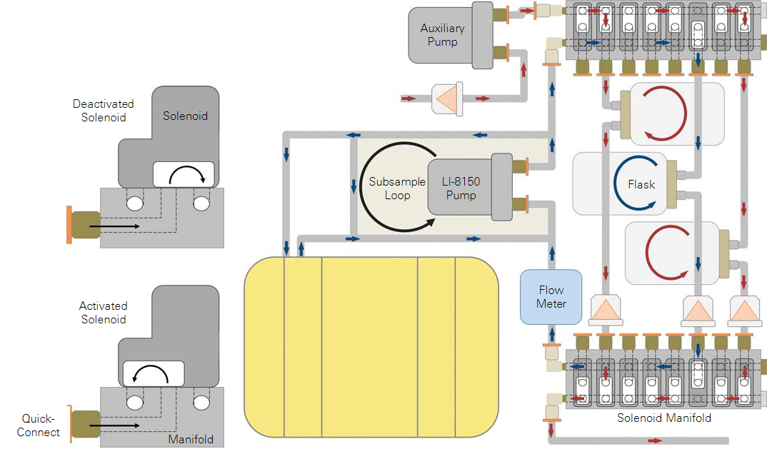
Some plumbing changes are required in order to configure the LI-8150 to continuously flush chambers with ambient air between sampling periods. Refer to Figure 5 to compare a normal LI-8150 with one modified for use with a flask system.
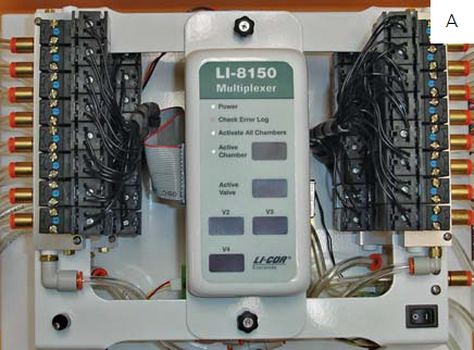
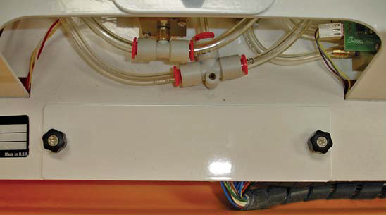
- Remove three of the brass plugs with a small adjustable wrench and one of the steel plugs with a 3/16 inch hex key.
- These plugs usually seal the inner side (the side closet to the LI-8150 control panel) of the solenoid manifolds, as shown in Figure 4, A. If modifying an eight port multiplexer, only remove the two brass plugs from the right hand upper and lower solenoid manifolds.
- Using an adjustable wrench, replace the three brass plugs with quick-connect elbows (part #300-07474) and the one steel plug with a quick-connect elbow (part #300-08118) (Figure 4, C).
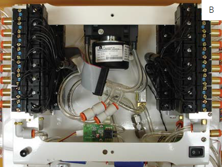
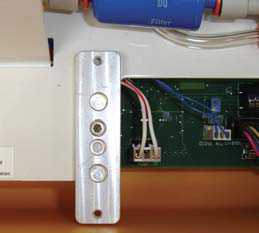
- Note that the metal base of the quick-connect fittings can be turned independently of the upper plastic portion without damaging the fitting. It may be helpful to insert a short piece of Bev-a-line tubing into the fitting to help hold it in position while tightening the metal base. For the sixteen port model, in order to add a quick-connect fitting to the lower left solenoid manifold, the hose connecting the lower left solenoid manifold to the pump will have to be temporarily removed. First, remove the two thumb screws that secure the control panel to the LI-8150 and the ribbon cable from the side of the control panel, and set the control panel aside (Figure 4, B). Carefully remove the hose from the quick-connect fitting by pressing down on the orange ring and pulling out on the hose. Rotate the fitting out of the way. After the second quick-connect fitting has been added replace the hose, seating it firmly in the fitting, and reinstall the control panel (Figure 4, C).
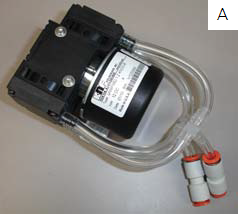
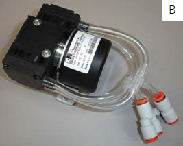
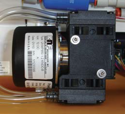
- Ventilation to the flasks is provided with an 8 L/min diaphragm pump (part #9981-173) that can be installed inside the LI-8150.
- If installing this pump in a sixteen port multiplexer remove the quick-connect straight union installed on the pump outlet and replace with a quick-connect “Y” fitting (part #300-03367) as shown in Figure 6, B. If installing in an eight port multiplexer no modification is needed (Figure 6, A).
- Before installing the pump, attach the pump assembly power cable (part #9981-177).
- This cable connects to the pump via a three-pin slip connector on the underside of the pump.
- Remove the cover plate from the instrument by loosening the two thumb screws (Figure 7, A).
- Mount the pump in the LI-8150 case by attaching the mounting plate to one of the two threaded holes normally used to attach the cover plate (Figure 7, B). Use one of the three 3/8 inch #6-32 hex cap screws (part #140-04315) and the 7/64 inch long arm hex key (provided) to attach the mounting plate to the LI-8150. Use the remaining two hex cap screws to attach the pump to the plate.
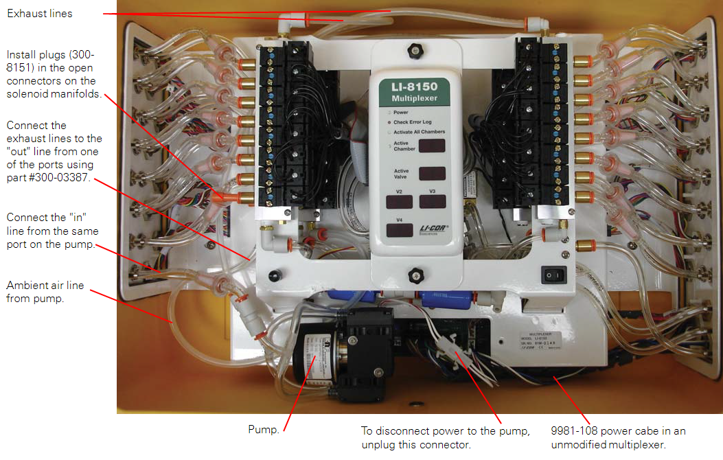
- Locate the main power supply cable inside the LI-8150 (part #9981-108; Figure 8).
- One end of this cable terminates in a four-pin slip connector connected to the main circuit board and the other in a four-pin Eurofast bulkhead mounted to the side of the LI-8150 case. Remove the cable by disconnecting the four pin slip connector from the circuit board and removing the nut on the outside of the LI-8150 from the Eurofast bulkhead.
- Install the pump assembly power cable into the multiplexer in place of the power cable removed in step 6 (Figure 8).
- When the new Eurofast bulkhead is installed the nut on the bulkhead needs to be tightened to 72 inch-lbs of torque to ensure a water tight seal.
- Cut two (one for an eight port multiplexer) 48 cm sections of Bev-a-line tubing.
- The two pieces of tubing are kept at the same length to help ensure that flow from the pump is split equally between the two manifolds. For a 16-port multiplexer insert one end of each hose into the “Y” fitting (part #300-03367) installed in step 3, and insert the other end into one of the quick-connect fittings added to the lower solenoid manifolds in step 2.
- For an eight port multiplexer connect the pump outlet with a single section of Bev-a-line tubing to the lower right hand solenoid manifold.
- There are two ways to configure the LI-8150 to vent exhaust from the flasks.
- Method 1: Dedicate a port on the multiplexer to supply air to the auxiliary pump and expel exhaust from the chambers.
-
- Disconnect the two urethane hoses coming from one set of port connections on the side of the LI-8150 from the solenoid manifolds.
- Insert 1/4 inch quick connect plugs (part #300-08151) into the open fittings on the solenoid manifolds (Figure 8).
- Connect the urethane hose from the “IN” connection of the port to the inlet of the auxiliary pump using a quick connect straight union.
- For a sixteen port model install a quickconnect “Y” fitting (part #300-03367) on the end of the “OUT” hose. For an eight port multiplexer, install a quick connect straight union (part #300-03123) on the “OUT” hose.
- Cut two 35.5 cm lengths of Bev-a-line tubing and connect the upper manifolds to the “Y” fitting with each length of tubing. For an eight port model use one length of tubing to connect the upper right hand manifold to the “OUT” hose.
- Method 2: If dedicating a port to vent chamber exhaust and supply air to the auxiliary pump is undesirable, the supply/exhaust lines can be routed out of the LI-8150 by leaving the case open. If using this method, a filter (part #301-08119) should be added before the pump inlet.

2.5 | Constructing chambers
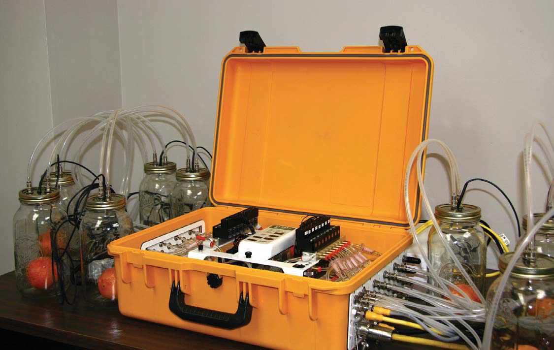
Flasks can be constructed from any gas tight containers, provided they meet the volume considerations discussed above and can be fit with connections for the LI-8150. Be careful with plastic containers as sorption of water vapor (and possibly CO2) by the container may affect the measured fluxes. Here we describe how to use 1.89 L glass canning jars (Ball Corporation, Daleville, IN) as sample chambers.
- With the lid removed from the jar, drill one 12 mm hole off center in the lid.
- Drill two 8 mm holes on either side of the lid, evenly spaced between the larger hole and the edge of the lid (Figure 9).
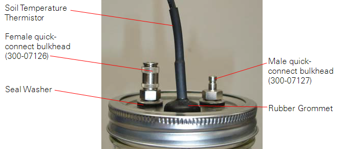
- Place a seal washer (part #167-07256) on the threaded portion of a female quick-connect bulkhead fitting (part #300-07125) and install it in one of the 8 mm holes using the nut and washer provided with the fitting.
- Repeat this procedure for the other 8 mm hole using a male quick-connect bulkhead fitting (part #300-07124) (Figure 11).
- Insert a rubber grommet (part #196-10534) into the 12 mm hole.
- Gently push a soil temperature thermistor (part #8150-203) through the hole in the grommet and then pull back slightly to seal it.
- A small amount of silicone grease (part #210-01958-1) can be used to ease insertion of the thermistor. To get a good seal the grommet should fit tightly in the hole and against the thermistor.
- Two sections of Bev-a-line tubing are required to connect each chamber to the LI-8150; cut the sections to the desired length and fit one end of each tube with a female quick-connect (part #300-07125) and the other end with a male quick-connect (part #300-07124).
- Measure and record the length of each tube.
- This information is very important and will be required later when the chamber volume is entered for use in the flux calculations.
- Attach the tubes to the fixtures on the lid of each flask, and then to the selected port on the LI-8150.
All ports that are not connected to a chamber, or used to supply/vent air from the flasks should remain capped with the black plastic caps supplied with the LI-8150. If these have been misplaced, replacement caps can be ordered from LI-COR using part #620-08298 and 620-08299. One of each will be needed for every unused port.
3 | Powering the system
The 8150-770 AC Power Supply can be used to supply power to the LI-8150 and LI-8100A, as well as the auxiliary pump used for continuously flushing the flasks. The 8150-770 is capable of providing up to 4.5 Amps at 12 VDC. When the auxiliary pump is installed as described in this application note the input voltage to the LI-8150 should not exceed a nominal 12VDC.
4 | Software Setup
There are some software configuration changes that must be made to use the LI-8150 and LI-8100A for multiplexed flask measurements. The bulk of these changes are made under the Chamber tab of the Multiplexer Configuration window and relate to defining the appropriate volumes and areas for the flux calculations.
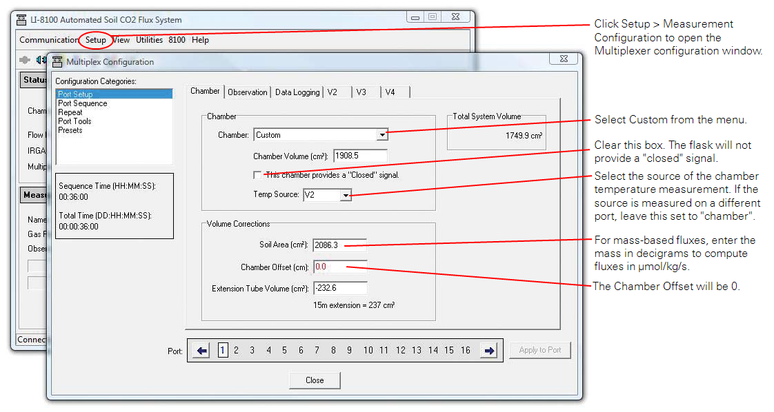
- Under the Setup menu in the main LI-8100A Windows interface software window, select Measurement Configuration (Figure 10).
- Select Port Setup from the Multiplexer Configuration window.
- In the Chamber tab, select Custom from the Chamber: menu and enter the chamber volume in cubic centimeters.
- Be sure to include the volume of the tubing used to connect the flask to the LI-8150 in the chamber volume1.
- Make sure the closed signal check box is unchecked and that the chamber offset is set to zero.
- Select the chamber air temperature source from the Temp Source menu.
- If the temperature source is measured by a different port, skip this and recompute with the correct temperature later. If measurements are made at near ambient temperatures a measurement of chamber air temperature may not be required.
- Soil Area (cm3) is where the sample area or mass is entered, depending on what basis fluxes will be calculated on.
- If a mass is entered in decigrams the final computed flux values will be in μmol kg-1 s-1, though they will still be labeled with the units μmol m-2 s-1.
- Extension Tube Volume (cm3) can be used to make a correction for the flask volume occupied by the sample by entering the sample volume here as a negative number.
- Under the Observation tab, Observation Delay and Purge Time should both be set to zero.
- While the flasks are continuously being purged between measurements, this is not the same as the purge time set in the software and is not under control of the LI-8100A. The values entered for the Deadband and Observation Length will be contingent on measurement conditions. Typically at moderate flux rates an observation length of two or three minutes works well. The deadband will depend on flask geometry and the flow rate during measurement, as well as the final CO2 concentration from the previous measurement, as there is some chamber-to-chamber carry over; see the LI-8100A Instruction Manual for determining an appropriate deadband length. Keep in mind that the observation length includes the deadband period.
- The settings under Data Logging, V2, V3, and V4 will be contingent on the experimental setup.
- Refer to the LI-8100A Automated Soil CO2 Flux System and LI-8150 Multiplexer Instruction Manual for information about setting the parameters under these tabs.
- Repeat steps three through nine for all ports where a chamber is connected.
- Select Port Sequence from the Multiplexer Configuration window and define the order in which the flasks will be sampled.
- Select Repeat from the Multiplexer Configuration window and define the sampling frequency.
- The instrument configuration can be saved from the Presets window.
5 | A measurement example using a twelve flask system
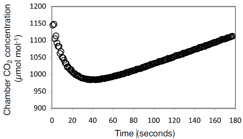
A twelve flask system was constructed following the methods outlined above and used to measure CO2 efflux from navel oranges. Flask air temperature was monitored during the measurements with an 8150-203 soil temperature thermistor installed in each flask as described above. Fluxes were calculated on a fresh weight basis and a volume correction was used to account for the flask volume occupied by the fruit. The flux measurements were made over a 3 minute period (observation length = 3 min). Due to significant carryover of CO2 from one flask to the next (Figure 11 and Figure 12) the first 60 seconds of each measurement were ignored in the flux calculations (deadband = 60 sec).
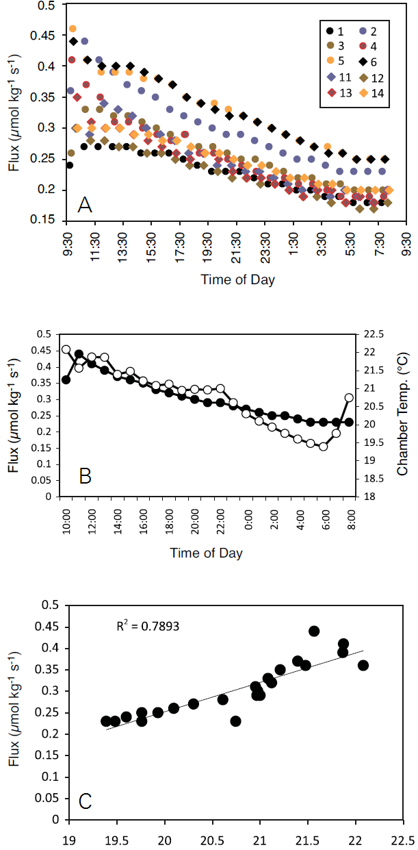
In total, ten navel oranges were monitored over a 24 hour time course. Flux rates were similar for all ten oranges measured with the multiplexed flask system, as shown in Figure 13, A. The rates declined steadily throughout the measurement period for all samples, and tracked a decline in chamber air temperature (Figure 13, B). The decrease in respiration rate was well correlated (r2 = 0.7893) with chamber air temperature over the measurement period (Figure 13, C), and is likely due to decreased metabolic activity within the fruit as it cooled (based on chamber air temperature Q10=7.8).
6 | Conclusions
The LI-8150 multiplexer is a highly adaptable instrument. When configured for multiplexed flask measurements it provides a means of rapidly sampling CO2 fluxes from multiple samples, and tracking fluxes over long time courses. While in the example shown we monitored respiration of detached fruit, similar systems have been applied in monitoring insect respiration (Nestel et al. 2007), respiration of isolated soil samples (Jones and Kielland 2002, Haney et al. 2008), and monitoring carbon fluxes from attached leaves and fruit (Araki et al. 1998, Kitano et al. 1997).
| Description | Part Number | Quantity |
|---|---|---|
| LI-8150 Multiplexer | LI-8150-16 or LI-8150-8 | 1 |
| LI-8100A Analyzer Control Unit | LI-8100A | 1 |
| AC-to-DC Power Supply | 8150-770-01 (discontinued) 8250-770 |
1 |
| Chamber Sensor Interface | 8150-661 | One per flask or one for every three soil temperature thermistors2 |
| Soil Temperature Thermistor | 8150-203 | One per flask |
7 | References
| 1 | Araki, T., M. Kitano, M. Hamakoga, and H. Egughi. 1998. Analysis of growth, water balance and respiration of tomato fruits under water deficit by using a multiple chamber system. Biotronics 27:61-68. |
| 2 | Haney, R., W. Brinton, and E. Evans. 2008. Soil CO2 respiration: Comparison of chemical titration, CO2 IRGA analysis and the Solvita gel system. Renewable Agri. And Food Sys. 23:171-176. |
| 3 | Jones, D. and K. Kielland. 2002. Soil amino acid turnover dominates the nitrogen flux in permafrost-dominated taiga forest soils. Soil Bio. & Biochem. 34:209-219. |
| 4 | Kitano, M., T. Araki, M. Hamakoga and H. Eguchi. 1997. On-line measurements of CO2 and H2O gas fluxes, sap flux and expansive growth in an intact tomato fruit. Biotronics 26:85-94. |
| 5 | Nestel, D., E. Nemny-Lavy and V. Alchanatis. 2007. Gasexchange patterns of Mediterranean fruit fly pupae (Diptera: Tephritidae): a tool to forecast developmental stage. Florida Entomologist 90:71-79. |