Vane Pump Upgrade Kit Instructions
Printable PDF: Vane Pump Upgrade Kit Instructions
(8100_AppNote_Vane_Pump_Replacement_ACU117.pdf)
Instructions for upgrading the vane pump.
This document describes how to install the vane pump upgrade (8100-929) in the LI-8100/A.
IMPORTANT NOTE: LI-COR has replaced the rotary vane pump in the LI-8100 with a more robust diaphragm pump. The 8100-929 Vane Pump Upgrade Kit can be field installed. Please note that this diaphragm pump is designed to be operated only at high speed, which is the optimal setting for this pump.
The only tools required to replace the rotary vane pump are a Philips head screwdriver and a knife. A narrow bladed flat screwdriver is helpful, but not necessary. Follow these steps to replace the rotary vane pump:
NOTE: Make sure that you are properly grounded to avoid any electro-static discharge events that can damage the internal components.
- Turn the instrument power off and remove the battery or other external power source.
- Open the Analyzer Control Unit case and remove the access panel by loosening the 4 thumbscrews.
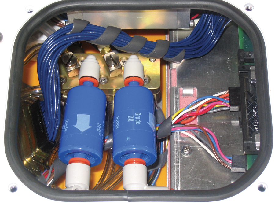
- Remove both air filters by pressing the orange part of the quick-connect fittings toward the white part of the connector and pulling each filter out.
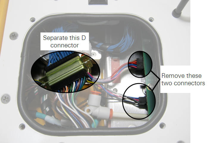
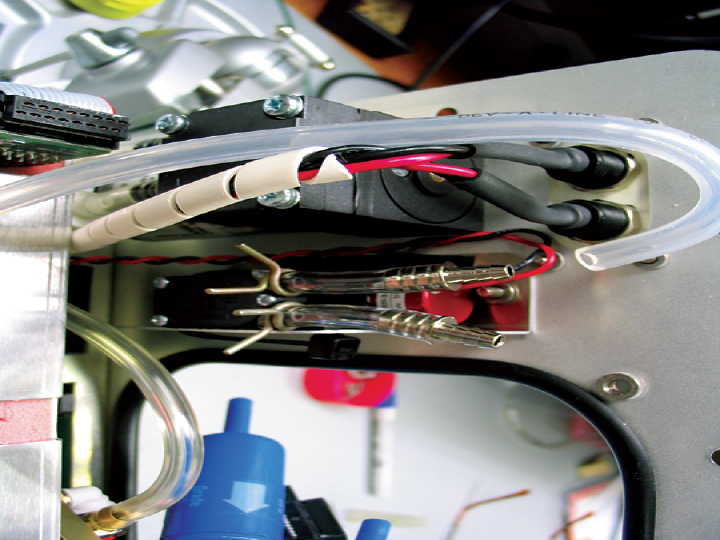
- There are 3 electrical connectors that must be removed. Two of them are on a single wiring harness, just to the right of the filter connectors; the third is at the left end of the bundle of blue cables, as shown. Pull straight out on the connectors to remove them.
- Remove the 2 screws from the top of the air manifold. It is not necessary to remove any of the hoses.
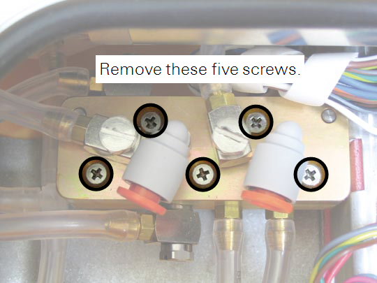
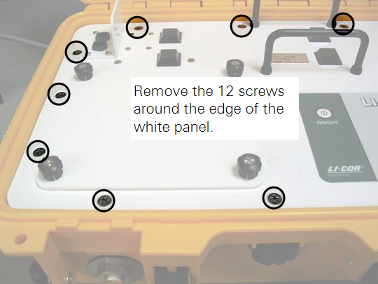
- Remove the 12 screws around the outer edge of the white panel.
- Lift the analyzer control unit from out of the yellow case. Note the position of the rotary vane pump. Turn the control unit upside down.
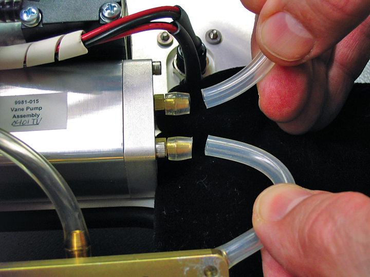
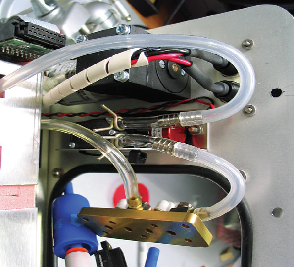
- Note the position of the 2 hoses attached to the pump; the hose attached to the manifold is attached to the Air In hose barb on the pump. Use a knife to cut the two hoses attached to the rotary vane pump. Cut the hoses as close to the hose barbs as possible.
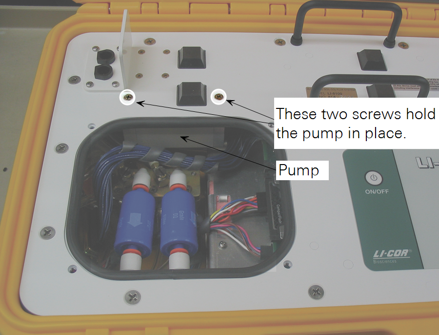
- Turn the control unit over again, and remove the 2 screws that hold the pump against the top mounting plate.
- Turn the control unit upside down, and note the location on the circuit board where the cable connector from the pump is attached. Pull on the wires to remove the connector from the circuit board. Discard the rotary vane pump.
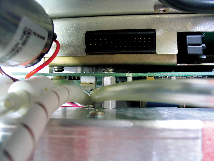
- The wire harness connector on the new diaphragm pump connects to the same connector on the circuit board that you identified in Step 10. It can be difficult to attach the new connector, as it is hard to reach. We have found that you can insert a long, thin, flat blade screwdriver (or other similar tool) into the hole in the center of the connector attached to the pump, and use the tool to help insert the connector. The connector on the pump is indexed, and will only fit in one direction.
- Hold the new pump against the control unit upper plate and attach with the 2 screws removed in Step 9.
- Reattach the 2 hoses. Make sure the hoses are seated completely over the hose barbs. This finishes the assembly for the new diaphragm pump.
- Re-assemble the manifold, reattach the air filters, and reassemble the LI-8100 case.
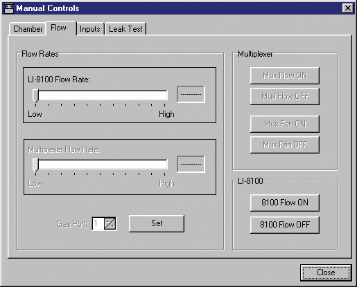
- The new diaphragm pump is designed to operate only at High speed. You can set the Flow Rate to High in the software.