
Printable PDF: Diaphragm Pump Upgrade Kit Instructions
(8100_InstallGuide_8150_9981-174_Pump_Upgrade_Kit_ACU120.pdf)
Instructions for installing the diaphragm pump.
IMPORTANT NOTE: LI-COR has replaced the rotary vane pump in the LI-8150 with a more robust diaphragm pump. The 9981-174 Diaphragm Pump Upgrade Kit can be field installed. The only tools required to replace the rotary vane pump are a Philips head screwdriver, 7/64” hex key (included), and a knife. The upgrade takes about 15-20 minutes to complete.
Follow these steps to replace the rotary vane pump:
NOTE: Make sure that you are properly grounded to avoid any electro-static discharge events that can damage the internal components.
- Turn the instrument power off and remove the power cable.
- Open the instrument case and remove the display panel by loosening the 2 thumbscrews. Unplug the ribbon cable attached to the display panel, and set the panel aside.
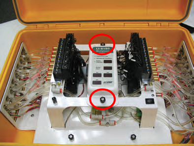
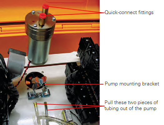
- Pull the tubing out of the two orange quick connect fittings attached to the pump. Pull the pump straight up and out of the mounting bracket.
- Loosen the 2 thumbscrews and remove the access panel. Unplug the wiring harness at the PUMP connector, and pull the pump and attached wire harness out of the instrument case.
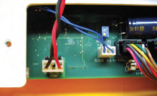
- NOTE: The wiring harness and connector might be difficult to remove while the connector is attached; if desired, you can cut the connector wires near the PUMP connector, pull the connector off, and then pull the wires out. Discard the pump and wiring harness. If there was a filter attached to the old pump, it can be discarded, too, as it is not needed with the new diaphragm pump.
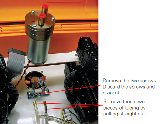
- Remove the 2 screws from the pump mounting bracket, and discard the old screws and mounting bracket. Remove the 2 short pieces of tubing and discard.
- Locate the new wiring harness (p/n 9981-176). Route the harness down through hole (solenoids in photo removed for clarity); you can route either end, as the connectors on both ends are the same. Route the harness underneath the mounting cage, and toward the access panel at the front of instrument case.
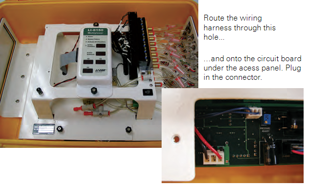
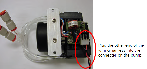
- NOTE: Be careful not to use tools that can damage the circuit board or other components when routing the wire harness. Plug the connector into the PUMP connector. Replace the access panel. Plug the other connector into the new pump. Note the orientation of the red and black wires on the two connectors.
- Install the new pump adapter plate (p/n 9881-204) at the location of the pump mounting bracket removed in Step 5. Use 2 of the 140-04315 cap screws and the 7/64” hex key to install the adapter plate, as shown in Figure 6.
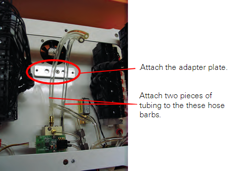
- Cut two 6” (15 cm) pieces of urethane tubing (p/n 222-00303) from the length provided. Attach these two pieces to the hose barbs (you removed two short lengths of tubing from these barbs in Step 5).
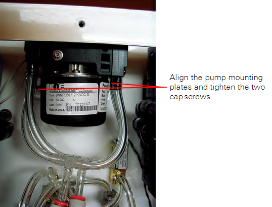
- Place 2 of the 140-04315 cap screws down through the pump mounting plate and align the pump over the adapter plate installed in Step 7. Use the 7/64” hex key to tighten the cap screws.
- The diaphragm pump assembly comes with tubing and quick connect fittings pre-installed. Note that there are 2 u-shaped tubing assemblies, one above the other. These assemblies attach to the two lengths of urethane tubing installed onto the hose barbs in Step 8.
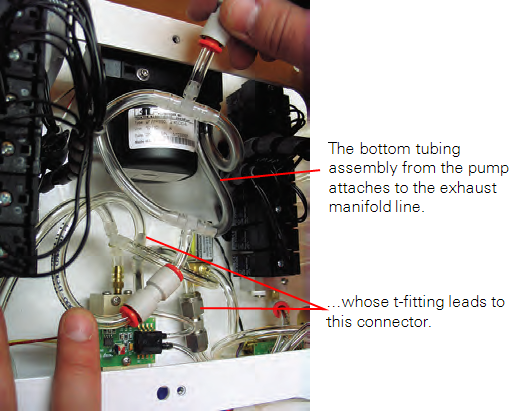
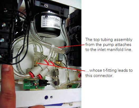
- The bottom tubing and quick connect fitting assembly from the pump attaches to the Exhaust manifold line. Push in on the orange rings on the quick connect fittings and slide the tubing into the connectors. The top tubing and quick connect fitting assembly from the pump attaches to the inlet line.
- This completes the pump assembly.
- Reinstall the ribbon cable onto the control panel, and install the control panel.