
8100-401 Chamber Control Kit Using LI-COR Automated Soil Gas Flux Chambers with a Custom Interface
(8100_TechNote_8100-104_Chamber_Control_Kit_ACU123.pdf)
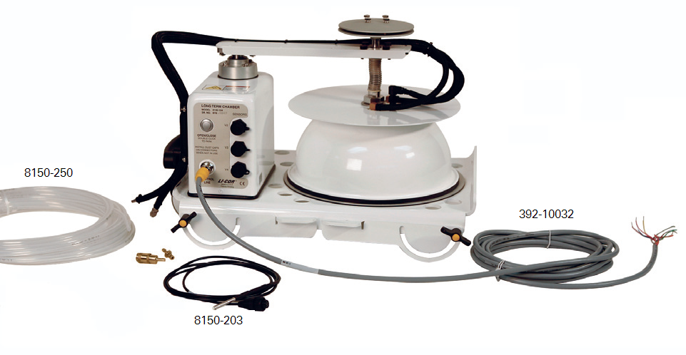
Instructions for using the chamber control kit.
| LI-COR Part Number | Description |
|---|---|
| 392-10032 | Turck to bare leads chamber control cable, 5 m long |
| 8150-203 | Soil temperature thermistor |
| 8150-205 | GS1 Soil Moisture Probe |
| 300-07124 | Male quick connect to 1/8” hose barb |
| 300-07125 | Female quick connect to 1/8” hose barb |
| 8150-250 | Bev-a-line tubing, 15 m long |
Pneumatic Connections
The 8100-104/C includes a baffle on one of the two hoses to the chamber bowl. This baffle serves to prevent liquid water from being sucked out of the chamber during a rain event and should be on the hose used to pull air from the chamber. On all new chambers this will be the hose that ends with the male quick connect fitting. New chambers also have ↓ or ↑ stamped on the fittings on the top of the chamber bowl, opposite the air in/out lines inside the chamber bowl, to identify the direction of air flow. Some older chambers were produced with two baffles. For these chambers, a baffle should only be placed on the fitting corresponding to the air leaving the chamber.
Actuating the Chamber
The 8100-104/C is opened and closed by a drive system built into the chamber. The drive is powered by +9 to 12 VDC supplied to the chamber at pin 10 of the control line connector, and initialization of the drive system is controlled by the status of pin 7 using Transistor-Transistor Logic (TTL). When the input to pin 7 goes high (5 VDC) the chamber will close; when the input goes low (0 VDC) the chamber will open.
Pin 5 of the control line connector provides a chamber stop signal that goes high (5 VDC) when the chamber is stopped in either the open or closed position. This pin will go low (<0.2 VDC) when the chamber is actively moving to either position.
Measuring Chamber Air Temperature
Chamber temperature in the 8100-104/C is measured by a thermistor embedded in the chamber temperature sensor. Excitation of the thermistor is handled by the chamber, and the signal output on pin 2 of the control line connector is a voltage proportional to the chamber air temperature. This signal is referenced to the analog ground on pin 3 of the control line connector.
To convert the output voltage (V in volts) to chamber air temperature (T in °C) the resistance of the thermistor (R in Ohms) must be found and a Steinhart-Hart equation applied.
1‑1

1‑2

The coefficients to use in the Steinhart-Hart equation for the chamber air temperature sensor are:
a = 1.069E-03
b = 212.07E-06
c = 90.1954E-09
Using the Auxiliary Sensor Inputs (V2, V3 and V4)
The 8100-104/C includes three built-in auxiliary sensor inputs (V2, V3 and V4) which can be used to measure soil temperature with an 8150-203 soil temperature sensor and soil moisture with an 8150-205 soil moisture sensor. Both are included in the 8100-401 Chamber Control Kit. Other sensors can be connected to these inputs; for additional details see the LI-8100A/LI-8150 Instruction Manual. The inputs are only active when the chamber supply voltage is greater than 10.5 VDC. At lower voltages the auxiliary inputs are disabled.
Measuring soil temperature using one of the auxiliary inputs is analagous to measuring chamber air temperature. For an 8150-203 connected to V2, a voltage proportional temperature is output on pin 4 of the control line connector referenced to the analog ground on pin 3. To convert the output voltage (V in volts) to temperature (T in °C), the resistance of the thermistor (R in Ohms) must be found and a Steinhart- Hart equation applied as shown above. The coefficients for the 8150-203, however, are different than those used for the chamber air temperature sensor. For the 8150-203 use:
a = 1.1259E-03
b = 2.3459E-04
c = 8.6329E-08
For soil moisture measurements using the 8150-205, a voltage proportional to the volumetric water content (VWC) is output referenced to analog ground. To operate the sensor, a switched 5 VDC excitation is required and is provided by the chamber. The excitation is active when pin 9 of the control line connector is set high (5 VDC), and stops when this pin goes low (0 VDC). To convert the voltage output from the sensor on one of the auxiliary inputs to VWC, use the following equation:
1‑3Θ = 4.94 × 10⁻⁴ × mV- 0.554
| Pin | Wire Color | Description | Type | Range | Arduino | CR1000 or CR3000 |
|---|---|---|---|---|---|---|
| 1 | White | Ground | Ground | - | GND | G |
| 2 | Brown | Chmber Temperature Signal | Analog | 0 to 5 VDC | A0 | SE1 |
| 3 | Green | Analog Ground | Ground | - | GND | AG |
| 4 | Yellow | V4+ | Analog | 0 to 5 VDC | A3 | SE5 |
| 5 | Gray | Chamber Stop Signal | TTL (out) | 0 to 5 VDC | A4 | SE2 |
| 6 | Pink | V3+ | Analog | 0 to 5 VDC | A2 | SE4 |
| 7 | Blue | Chamber Open and Close Signal | TTL (in) | 0 to 5 VDC | 3 | C! |
| 8 | Red | V2+ | Analog | 0 to 5 VDC | A1 | SE3 |
| 9 | Orange | Switched 5V supply control | TTL (in) | 0 to 5 VDC | 2 | C2 |
| 10 | Tan | Voltage supply to chamber | Supply | 9 to 12 VDC | Vin* | 12V |
| Shield | Bare | Ground | Shield | - | GND | G |
This assumes the Arduino is powered via Vin. The auxiliary inputs will only be active if the supply to Vin is between 10.5 and 12 VDC. If Vin is supplied with less than 12 VDC the auxiliary inputs may dip low while the chamber is moving.
Example Control Platforms/ Programs
Two example control programs are available from LI-COR that demonstrate how to control an 8100-104/C using two different commonly available hardware platforms. Both platforms provide interfaces suitable for interacting with the chamber and can be used to integrate chamber control with data from a standalone analyzer or other sensors.
One example shows how to use a Campbell Scientific CR1000 or CR3000 to actuate the chamber, and access the chamber’s auxiliary inputs and chamber temperature sensor. Flags are included that can be accessed through LoggerNet’s Ports and Flag window to actuate the chamber, start and repeat measurements and activate the excitation used by a soil moisture sensor.
The other example is written for the Arduino and is functionally similar to the CRBasic program provided for the CR1000/ 3000. It uses a button connected to one of the Arduino’s analog inputs to trigger a measurement cycle, and includes feedback via the Arduino’s serial monitor. This version has been tested on the Arduino Uno or Mega 2560.
For both programs, more details on their use and functionality can be found embedded as comments in the respective program.
The example control programs can be downloaded at:
https://licor.app.boxenterprise.net/s/iqum7ywbj7gwzota3v43dtnrb4bo8hd6
Changing the 8100-104/C Chamber Open Position
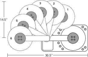
The default chamber open position is approximately 180° from the closed position. There are, however, five additional open positions (below) that can be programmed using the Open/Close button on the chamber control panel. This can be useful for areas where the terrain, or obstructions, don't permit the full 180° of movement. To change the open position:
- Press and hold the Open/Close button for 5 seconds. Wait a few moments while the chamber positions itself.
- Press the Open/Close button one time to move the chamber to its first open position (#5 in the diagram below). Continue to press the button one time to move the chamber to each of the other five open positions.
- When the chamber is in the desired open position, hold the Open/Close button for 5 seconds again; the chamber will “remember” this position until it is reprogrammed.
The 8100-104/C Long-Term Chamber has six programmable open positions.
Press the Open/Close button twice in quick succession to “park” the chamber; the chamber raises slightly to prevent compression of the chamber gasket.
IMPORTANT! We recommend that you “park” the chamber before transport or long-term storage of the chamber.
Relevant Part Numbers
- 8100-104 Long-Term Chamber
- 8100-104C Clear Long-Term Chamber
- 8100-401 Chamber Control Kit
- 8100-910 Clear Chamber Bowl Assembly (kit to convert 8100-104 to 8100-104C)
- 8100-911 Opaque Chamber Bowl Assembly (kit to convert 8100-104C to 8100-104)
- 8100-664 Trace Gas Sampling Kit
- 6581-044 Soil Collar (20 cm)
Chamber Specifications
8100-104 Long-Term Chamber
Volume: 4076.1 cm3
Soil Area Exposed: 317.8 cm2 (49.3 in2)
Dimensions: 48.3 cm L x 38.1 cm W x 33.0 cm H (19" x 15" x 13")
Weatherproof Rating: Tested to IEC IP55 standard
Air temperature thermistor:
Operating Range: -20 to 45 °C
Accuracy: ± 0.5 °C over 0-70 °C
Cable length: Purchased separately
Weight: 5.9 kg (13 lb.)
8100-104C Clear Long-Term Chamber
Volume: 3876.1 cm3
Soil Area Exposed: 317.8 cm2 (49.3 in2)
Dimensions: 48.3 cm L x 38.1 cm W x 33.0 cm H (19" x 15" x 13")
Weatherproof Rating: Tested to IEC IP55 standard
Air temperature thermistor:
Operating Range: -20 to 45 °C
Accuracy: ± 0.5 °C over 0-70 °C
Cable length: Purchased separately
Weight: 5.9 kg (13 lb.)