Printable PDF: Measuring Small Gas Volumes with the LI-8100A
(8100A_TechNote_Small_Volume_Measurements_ACU124.pdf)
Instructions for measuring small gas volumes with the LI-8100A.
The LI-8100A Analyzer Control Unit is designed to be used with accumulation chambers to make measurements of soil CO2 flux. The Control Unit contains an infrared gas analyzer (IRGA) capable of measuring both CO2 and water vapor, a sampling pump and integrated data logging hardware. The LI-8100A can also be used as a stand-alone gas analyzer for other applications, such as determining CO2 concentration of small air samples. For applications where only a small sample of gas is available (10 ml or less) it is not possible to flow the gas continuously through the analyzer. In these applications, samples are injected into a carrier gas stream flowing continuously through the LI-8100A. The carrier gas is typically free of CO2, provided from either a tank of compressed gas or chemical scrubbers. The peak concentration observed after injection is used to determine the concentration of the sample gas by comparing it to a calibration curve generated from a range of known samples.
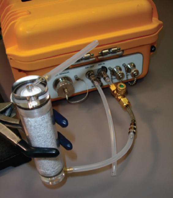
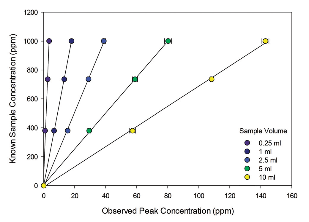
The 8100-664 Trace Gas Sampling Kit provides a convenient means for injecting gas samples. The kit connects to the Air In port on the LI-8100A, between the analyzer and the source of carrier gas (Figure 1). Small volume samples can be injected from a syringe through the septum on top of the kit. Both sample volume and concentration of the sample gas affect the observed peak height; for smaller volumes and/or lower concentrations, peaks will be smaller. In the example calibration curves shown in Figure 2, the effect of sample volume on peak height is obvious. For a carrier gas, N2 or CO2-free air provided by a tank of compressed gas is optimal. When using tank gas, the LI-8100A internal pump should be turned off during measurements and a rotameter should be placed in-line between the tank’s regulator and the LI-8100A Air In port to ensure flow is constant and known. Flow rates between 0.5 and 1.5 LPM work well for making injections into the LI-8100A. It should be noted though, that for sample volumes less than that of the LI-8100A’s optical bench, as flow rate increases the observed peak height will decrease for any given sample size and concentration.
It is possible to provide the carrier gas by means of chemical scrubbers and the internal pump of the LI-8100A. This method does come with some precautions, however. When the LI-8100A pump is used to provide flow in this application it places the injection septum under negative pressure, allowing ambient air to be drawn in as the septum is pierced. This can result in a short period of instability in CO2 concentration as the parcel of ambient air moves through the IRGA. If this method is used it is advisable to delay injecting the sample for a few moments after piercing the septum with the syringe to allow the instrument to return to a stable baseline. Also, because the efficacy of the chemical scrubbers decreases with use, recording a pre-injection base line CO2 concentration and subtracting this from the observed peak concentration will improve the repeatability of the measurements. To generate a calibration curve (Figure 2), samples of known concentration are injected under the same conditions as will be used for the unknown samples. It is important to match carrier gas flow rate and sample size exactly between known and unknown samples while generating the calibration curve, and to use a consistent injection rate for all gas samples. A line is fit to the observed peak height versus known concentration and this relationship is used to determine the concentration of the unknown samples. The known concentrations used to generate the calibration curve should cover the entire range of expected concentrations for the unknown samples.