
Measuring High CO2 Flux Rates
Basics
In a closed chamber system such as the LI-8100A Automated Soil CO2 Flux System (for details about chamber measurements, see Welles, et al., 2001 or LI-COR Application Note #124) soil CO2 flux is given by
1

where Fc is the soil CO2 flux rate (μmol m-2 s-1), V is volume (cm3), P0 is the initial pressure (kPa), S is soil surface area (cm2), T0 is initial air temperature (°C), R is the Universal Gas Constant, and dC/dt is the initial rate of change in CO2 mole fraction (μmol mol-1 s-1). In this equation the dilution effect of water vapor on CO2 concentration are being ignored. For a more detailed discussion, refer to the LI-8100A Automated Soil CO2 Flux System & LI-8150 Multiplexer Instruction Manual, available on LI-COR’s website. From this equation, it can be seen that for a given soil CO2 flux, the initial rate of increase of chamber CO2 concentration (dC/dt) depends on the ratio of chamber volume to soil area (V/S). A larger V/S ratio will lead to a slower rise in chamber CO2 concentration. At very high rates of ground CO2 emissions, CO2 concentrations in the chamber can quickly over-range the CO2 gas analyzer. With the introduction of the LI-8100A, the gas analyzer operating range increased from a maximum of 3,000 ppm to about 20,000 ppm CO2. The use of a double rectangular hyperbolic calibration function enables the LI-8100A to retain the same high sensitivity at ambient concentrations for measuring low biogenic rates of emission while maintaining good accuracy at the high concentrations (± 1.5% of reading). Under biogenic conditions, and to avoid perturbing the soil CO2 profile excessively, the chamber CO2 concentration during measurement is typically allowed to increase only slightly above ambient (~380 ppm). However, at high flux sites such as those mentioned above, chamber CO2 concentration can rise thousands of ppm above ambient in less than a minute, and the higher operating range of the LI-8100A system will be required. From the flux equation above, it can be estimated that with the older LI-8100 System, which uses a polynomial calibration function and has a CO2 measurement range of up to around 3,000 ppm, it is possible to measure maximum CO2 fluxes of about 300 μmol m-2 s-1. Note that it is possible to upgrade the LI-8100 analyzer to measure in the same range as the LI-8100A (contact LI-COR for details).
Using the LI-8100A at a High CO2 Flux Site
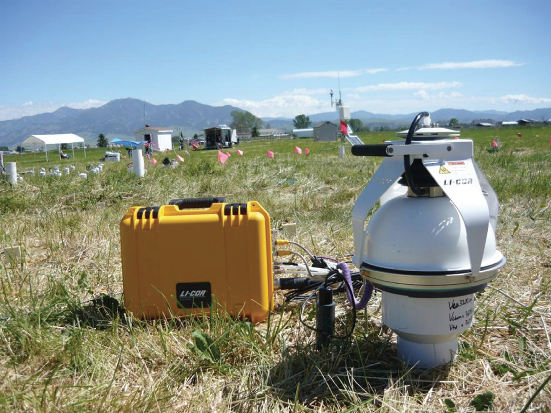
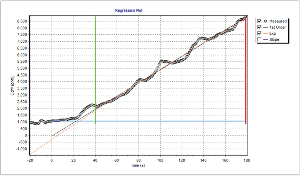
Figure 1 shows a regression of chamber CO2 concentration versus time. This measurement was taken at The University of Montana Zero Emission Research and Technology (ZERT) site in July of 2010, immediately over a leak point, and two days after starting to inject CO2 into a perforated underground pipe. The ZERT site was established for testing leak detection techniques for use at CO2 sequestration sites – (see ZERT website for details: http://www.montana.edu/zert/). This measurement was taken with the LI-8100A system, using the 8100-102 10 cm diameter soil CO2 flux chamber. It can be seen that chamber CO2 concentration exceeded the 20,000 ppm calibration range of the gas analyzer after only about 50 seconds from the chamber closing down over the installed soil collar. Using the chamber CO2 concentration data between 20 to 50 seconds after closing, ground CO2 flux was computed to be just over 1,900 μmol m-2s-1. Using non-linear regression, the soil CO2 concentration near the surface (Cx) was estimated to be about 140,000 ppm (see LI-8100A Instruction Manual for more explanation). Pure CO2 was being injected through the perforated test pipe fixture about 2 m below the surface. During this measurement, the atmospheric CO2 concentration (Co) a few centimeters above the collar was over 2,000 ppm.
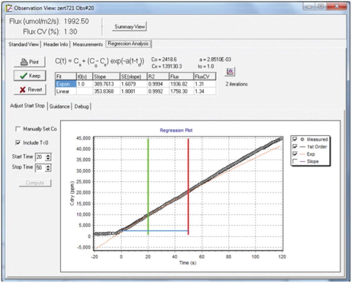
In this measurement we allowed an initial 20 second Deadband for chamber volume mixing after closure over the collar (see LI-8100A Instruction Manual) and another 30 seconds of data collection (30 data points) for curve fitting to determine the initial rate of increase of chamber CO2 concentration (dC/dt) for calculating the soil CO2 flux. For this analysis we did not include CO2 concentrations above 20,000 ppm, as the gas analyzer is not calibrated above this point. Also, because of the very high chamber concentrations involved, it is important to install the collars deep enough into the soil to prevent CO2 from diffusing out around the edges of the collar when the chamber concentration increases above the CO2 concentration in the surface layer of the soil. A soil CO2 flux of about 2,000 μmol m-2 s-1 is about the highest rate of emission that can be reliably measured using a standard LI-8100A System, since a minimum of about 50 seconds of data is required to allow for chamber volume mixing and collecting and an adequate number of data points for curve fitting. Fluxes higher than this would cause chamber CO2 concentrations to rise beyond the operating range of the system CO2 gas analyzer before an adequate number of readings can be taken. In making this statement, we assume that there is an approximately linear increase in chamber CO2 concentration with time.
As a first order approximation this is true, since the soil CO2 concentration (Cx) at high efflux sites is likely to be much higher than the maximum operating range of the LI-8100A gas analyzer. Below we present a simple way to modify the chamber volume to soil area ratio for measuring CO2 fluxes that are up to about 8,000 μmol m-2 s-1; or about a thousand times larger than typical biogenic fluxes. Modifying an LI-8100A System for Measuring High CO2 Flux Rates Using the closed chamber flux equation given above, we discussed earlier how for a given soil CO2 flux, increasing the chamber volume or decreasing the soil area could lower the rate of increase of chamber CO2 concentration (dC/dt) to provide more time for a flux measurement to be completed before the gas analyzer overranges. However, since the air flow available for mixing the chamber volume is limited, we cannot simply increase the chamber volume or there will be inadequate chamber volume mixing. The air flow available from the LI-8100A Analyzer Control Unit is about 1.5 LPM. With the CO2 flux chamber attached directly to the LI-8100A Analyzer Control Unit, employing a chamber with a volume much larger than the 20 cm diameter chamber (volume ~5,000 cm3) could result in inadequate mixing. Thus, without additional measures such as installing a mixing fan inside the chamber, the chamber volume should not be increased significantly. The chamber soil interface area, however, can be reduced. The photo in Figure 2 shows an adapter which makes it possible to use the 8100-103 20 cm Survey Chamber on a 10 cm diameter collar. This adapter reduces the soil area being measured from about 315 cm2 down to about 80 cm2 providing a 4-fold increase in the chamber volume-to-area ratio and a corresponding 4-fold increase in the maximum CO2 flux that can be measured with the LI-8100A System. If an additional mixing fan were to be installed inside the chamber, or if using the LI-8150 Multiplexer (which has a larger capacity pump for providing an air flow of ~3 LPM), the chamber volume could be increased further for measuring even higher ground CO2 fluxes.
The collar adapter shown above in Figure 2 was made using a PVC pipe ‘reducer’ fitting found at hardware or home improvement stores. This reducer fitting had an internal diameter of 16 cm at the large end and a 10.7 cm internal diameter at the smaller end. A short, 2.5 cm length of the 20 cm diameter collar was glued onto the large end of the reducer using a circular plate cut out of a sheet of plexiglass. A ring of foam gasket material was glued inside the reducer funnel at the top end of the 10.7 cm diameter section (below, and top right).
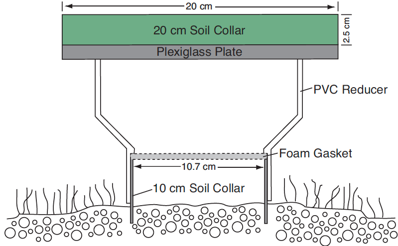
The total volume of this funnel-shaped adapter was just over 3000 cm3. This is about the same volume as a 20 cm diameter collar sticking out 10 cm above the soil. So the overall volume is not larger than if using the 20 cm chamber on a 10 cm tall collar. The mixing in this adapter/ chamber combination volume was barely sufficient. A short piece of tubing extending from the inlet port inside the chamber dome, down towards the soil collar would have improved the chamber volume mixing.
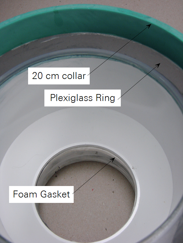
Figure 4 below shows what the CO2 concentration vs. time plot might look like if there is insufficient mixing of the chamber volume.
Conclusions
Using the LI-8100A System (or an upgraded LI-8100) it is possible to measure soil CO2 fluxes of up to about 2,000 μmol m-2 s-1. The total measurement time including a 20 second Deadband should be kept to less than about 60 seconds for measuring such a rate. The measurement chamber volume to soil area ratio can be modified to further increase the maximum CO2 flux that can be measured to about 8,000 μmol m-2 s-1. Installing the soil collars to adequate depth is important for preventing under-estimation of the ground CO2 flux which can be caused by CO2 diffusing out of the chamber/collar system as the chamber CO2 concentration rises to high levels.
Reference
| 1 | J. M. Welles, T. H. Demetriades-Shah, D. K. McDermitt. Considerations for measuring ground CO2 effluxes with chambers. Chemical Geology 177 (2001) 3-13. |