
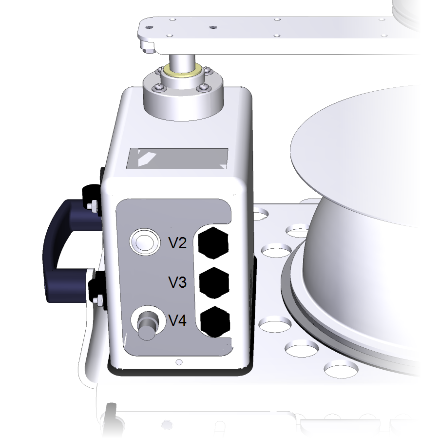
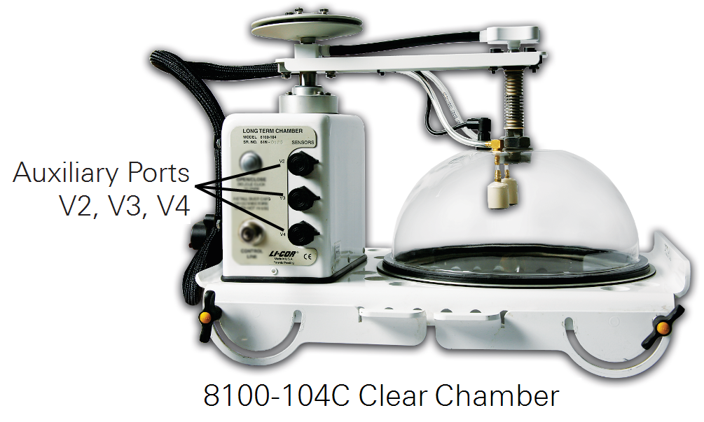
The 8100-104 and 8100-104C Long-Term Chambers have sockets for connecting three auxiliary sensors. The sealed connectors, labeled V2, V3, and V4, are 0-5 V inputs. Data from these sensors are logged in the data file under the headers V2 to V4 (voltage inputs) and the headers T1 to T4 (thermocouple inputs). The data under the header V1, when using a multiplexer, is the multiplexer pump voltage.
Soil temperature and soil moisture probes that are pre-wired for direct connection to the 8100-104/C are available from LI-COR.
You can connect auxiliary sensors to each chamber, or you can use measurements from one auxiliary sensor for all chambers by enabling Fix to port. When you enable Fix to port for a sensor, its data will be recorded for every port’s observation. This works for sensors with continuous excitation voltages, such as a soil temperature sensor or a quantum sensor. However, soil moisture sensors require a switched excitation voltage. The chamber’s switched excitation voltage is only turned on when that chamber is being sampled, so Fix to port does not work with soil moisture probes.
Connecting the GS1 soil moisture probe
The GS1 soil moisture probe can be connected directly to the long-term chamber V2, V3, or V4 inputs. The 8150-205 model has a connector that attaches directly to the long-term chamber V2, V3, or V4 input. To connect it, simply plug it into the terminal, then configure the software.
![]()
In the PC Software:
Click Chamber Measurement (Ctrl + M) > Port Setup, then select the corresponding voltage tab.
Select Soil Moisture Probe and enter m: 0.494 and b: -0.554.
![]()
In the App:
Tap LI-8100A > Auxiliary Inputs, then select the corresponding voltage input.
Select SM (soil moisture) and enter Slope: 0.494 and Offset: -0.554.
You can also perform soil-specific calibration to obtain linearization coefficients; refer to the GS1 instruction manual for more information.
Connecting the EC-5 soil moisture probe
The ECH2O soil moisture probe can be connected directly to the long-term chamber V2, V3, or V4 inputs. The 8150-202 model has a connector that attaches directly to the long-term chamber V2, V3, or V4 input. To connect it, simply plug it into the terminal, then configure the software.
![]()
In the PC Software:
Click Chamber Measurement (Ctrl + M) > Port Setup, then select the corresponding voltage tab.
Select Soil Moisture Probe and enter1 m: 0.488 and b: -0.272.
![]()
In the App:
Tap LI-8100A > Auxiliary Inputs, then select the corresponding voltage input.
Select SM and enter1 Slope: 0.488 and Offset: -0.272.
Connecting the 8150-203 soil temperature probe
The 8150-203 soil temperature probe is a soil temperature sensor (part number 8100-203) without the cable adapter (part number 9981-150). The cable adapter should be removed when the probe is connected directly to a long-term chamber V2, V3, or V4 inputs. To connect it, simply plug it into the terminal, then configure the software.
![]()
In the PC Software:
Click Chamber Measurement (Ctrl + M) > Port Setup, then select the corresponding voltage input channel.
Select Thermistor Input and click Set to Default or enter the coefficients:
![]()
In the App:
Tap LI-8100A > Auxiliary Inputs, then select the corresponding voltage input channel.
Select Therm and tap Set to Default enter the coefficients:
a=1.1259e-3
b=2.3459e-4
c=8.6329e-8
Connecting the Delta-T ThetaProbe
The 8150-204 Delta-T ThetaProbe is compatible with voltage channels 2-4. The 8150-204 model has a connector that attaches directly to the long-term chamber V2, V3, or V4 inputs. To connect it, simply plug it into the terminal, then configure the software.
![]()
In the PC Software:
Click Chamber Measurement (Ctrl + M) > Port Setup, then select the corresponding voltage input channel.
Select Soil Moisture Probe and enter m (Slope) and b (Offset) from Table 5‑1.
![]()
In the App:
Tap LI-8100A > Auxiliary Inputs, then select the voltage input channel.
Select SM (Soil Moisture) and enter Slope and Offset from Table 5‑1.
The ThetaProbe uses different linearization coefficients, based on the organic content of the soil into which the probe is inserted. In general, if the soil is classified as a mineral soil, with < 7% organic content, the probe uses one set of coefficients, and if the soil is classified as an organic soil, with > 7% organic content, the probe uses a second set of coefficients.
It is possible to perform soil-specific calibration of the soil moisture probe to obtain linearization coefficients; refer to the ML2x ThetaProbe instruction manual for more information.
Connecting the LI-190R Quantum Sensor
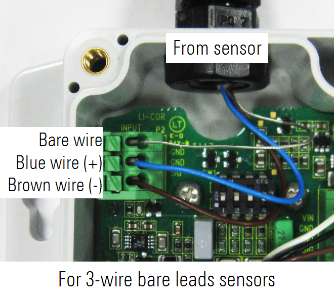
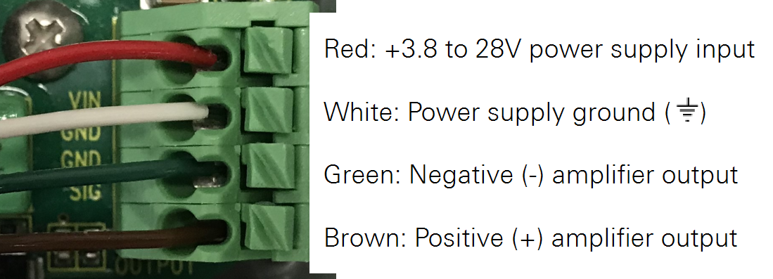
The LI-190R-BL-2 Quantum Sensor with 2420-BLS Amplifier has four wire leads connected to a terminal for connection to a long-term chamber.
2420-BLS Amplifier Gain Settings
The amplifier provides 15 discrete gain settings to accommodate a variety of full-scale light intensities and full-scale voltage ranges. This section shows how to determine the correct gain setting for your application. Gather the following information:
- Calibration constant for your light sensor (C)
- Maximum full-scale light intensity to be measured (Imax)
- Full-scale input voltage of the datalogger (Vmax = 5.0 V for the LI-8100A Automated Soil CO2 Flux System)
Follow these steps:
- Calculate the ideal amplifier gain (Gideal).
-

- Example: Consider a quantum sensor installation with the following parameters:
-
- Sensor calibration constant: C = 6.5 μA per 1000 μmol m–2 s–1
- Full-scale light intensity: Imax = 2000 μmol m–2 s–1
- LI-8100A full-scale channel voltage: Vmax = 5.0 V
-

- Select the gain setting (G) from the Gain Settings Table (page 2) that is less than or equal to the ideal gain from step 1.
- Example: The ideal gain computed in step 1 is Gideal = 0.3846 V μA–1. On the table, the closest actual gain that is less than or equal to this value is G = 0.375 V μA–1.
- Use a number 2 Phillips screwdriver to remove the amplifier lid. Alternate the four screws, pulling the lid up as you go so that the screws do not bind with the lid.
- Using a small screwdriver, set the switches in the center of the circuit board. Use the switch settings from the gain settings table that correspond to the amplifier gain determined in step 2.
- Example: The gain determined in step 2 (G = 0.375 V μA–1) requires all switches to be in the off position:

|
G = 0.375; all switches off | 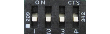
|
| DIP Switch | Gain (V μA–1) | DIP Switch | Gain (V μA–1) |
|---|---|---|---|
|
|
G = 0.375 (all switches off) |

|
G = 0.175 |

|
G = 0.350 | 
|
G = 0.150 |

|
G = 0.325 | 
|
G = 0.125 |

|
G = 0.300 | 
|
G = 0.100 |

|
G = 0.275 | 
|
G = 0.075 |

|
G = 0.250 | 
|
G = 0.050 |

|
G = 0.225 | 
|
G = 0.025 |

|
G = 0.200 | 
|
Do Not Use (all switches on) |
- Re-install the lid. Torque the screws to 0.45 Nm (64 oz-in.) if using a torque screwdriver.
- Calculate the voltage multiplier (M). The voltage multiplier is used to convert the voltage measured by the datalogger into a light intensity. For Quantum sensors, the units for M are μmol m–2 s–1 V–1.
-

- Example: Calculate M using G = 0.375 V μA–1 from step 2 and C = 6.5 μA per 1000 μmol m–2 s–1 from step 1:
-

Connecting the LI-190R and amplifier to a chamber
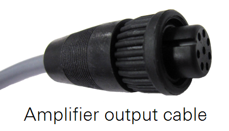
The 2420-BLS amplifier comes prewired with an output cable. Plug this cable into one of the auxiliary sensor ports on the side of the long-term chamber.
![]()
In the PC Software:
Click Chamber Measurement (Ctrl + M) > Port Setup, then select the V4 tab.
Select General Purpose Input and enter the slope calculated earlier for m and b: 0.0.
If you are using only one quantum sensor, select Fix to port and enter the port number of the chamber that has the sensor attached.
Click Apply to Port.
![]()
In the App:
Tap LI-8100A > Auxiliary Inputs, then select the voltage input to configure.
Select GP (general purpose) and enter Slope (m): calculated earlier and Offset: 0.0.
If you are using only one quantum sensor, select Fix to port and enter the port number of the chamber that has the sensor attached.
Tap Apply to Port.
Connecting other sensors
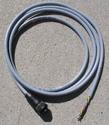
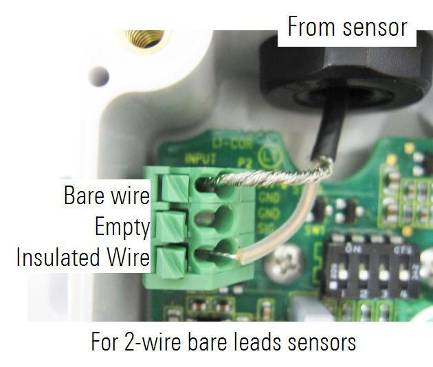
Other sensors with bare wire leads are connected with the adapter cable (part number 392-08577). The software is configured by setting the slope and offset as needed to scale the readings from the sensor.
It may seem obvious, but it is worth pointing out that when the multiplexer is attached to the LI-8100A, the auxiliary sensor interface cannot be attached to the LI-8100A.
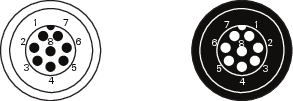
| Connector on the 8100-104/C Long-Term Chamber | Connector on the 392‑08577 Cable |
|
|
| Pin Number | Signal | Wire Color |
|---|---|---|
| 1 | 0 v – 5 v In (+) | Brown |
| 2 | 5V_Ref Out (4 mA) | Pink |
| 3 | +5 V Out (100 mA) | Blue |
| 4 | N/C | Grey |
| 5 | Unreg Out (50 mA) | Red |
| 6 | Switched +5 V Out (30 mA) | Yellow |
| 7 | 0 v – 5 v In (-) | Green |
| 8 | Gnd | White |