
The LI-8150 Multiplexer contains a pump and tubing to transport the sample gas from one of the chambers (up to 16) to the IRGA in the LI-8100A. Air flows to and from the chamber while maintaining the ambient pressure in the IRGA.
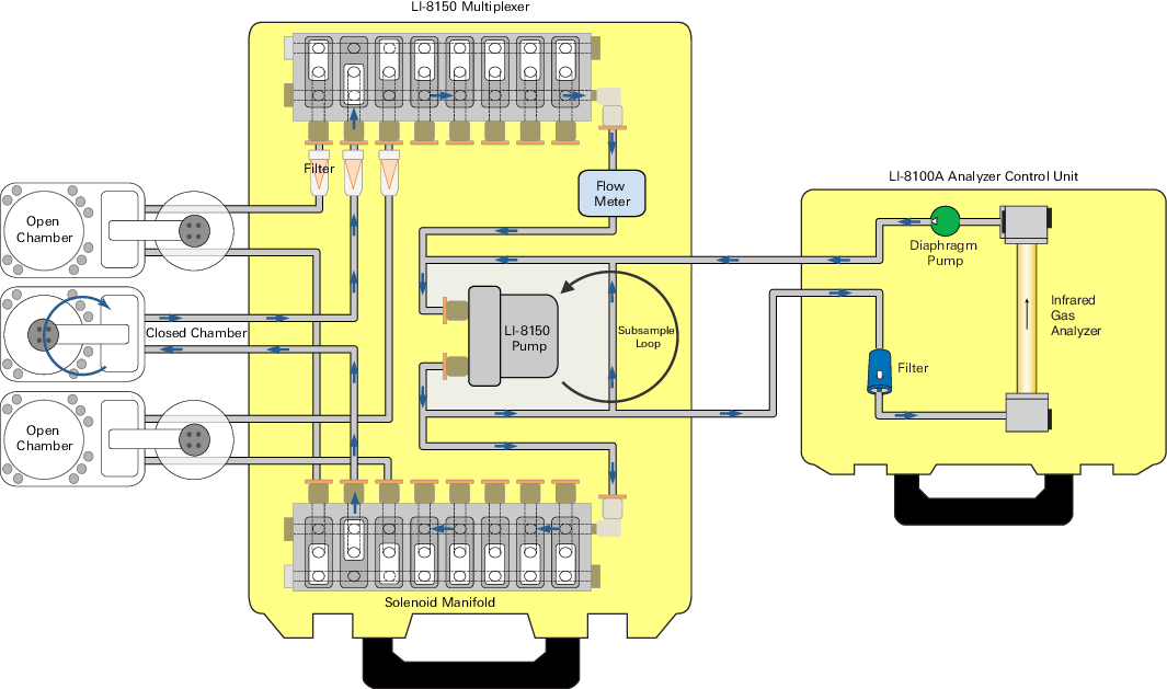
A diaphragm pump circulates the sample gas to and from the multiplexer and the closed chamber. A flow sensor detects flow in the ‘chamber loop’ (between 1.5 and 3.5 lpm in normal operating conditions). The pump also circulates flow in a ‘subsampling loop’, as it is in-line with both parallel loops. Flow restrictors in the ‘subsampling loop’ restrict flow in comparison to the ‘chamber loop’ to control the pressure in the LI-8100A IRGA. The LI-8100A, in turn, samples air from the ‘subsampling loop’ using its own pump. Sample gas from the chamber is filtered before it enters the solenoid, and again in the LI-8100A before it enters the IRGA.
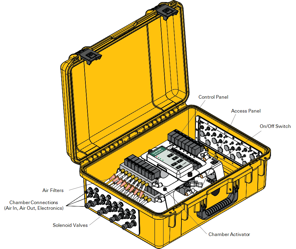
The LI-8150 has connections for up to 8 chambers on each side. The left side shown above (optional) has only chamber connections; the right side (not pictured) also has power and LI-8100A connections. The power switch, chamber actuator, and indicator panel are inside the LI-8150.

Power – Illuminates when power is applied to the instrument, and the power switch is turned On.
Check Error Log – Illuminates when an error condition is detected (a chamber failed to close, flow rate is too low, etc.). The Error Log can be viewed in the Windows application software, under the View menu, and in the mobile app by pressing the “E” indicator when present.
Activate All Chambers – Illuminates when Chamber Actuator Button is pressed. All connected chambers will close in series (4 at a time); (1-4), (5-8), (9-12), and (13-16).
Active Chamber – Displays chamber that is currently performing a measurement.
Active Valve – Displays currently active (open) solenoid valve. When a measurement is being performed, this will always match the Active Chamber. When the instrument is idle, however, a valve can be operated independent of the chamber(s).
V2-V4 – Shows the port from which the indicated voltage output is coming.