
If the bellows on the Survey Chamber is punctured or is otherwise damaged and develops a leak, it will not operate properly. You can replace it with the optional Bellows Kit (part number 8100-623).
- Remove the handle from the chamber.
- When the handle is in a horizontal position, it can be removed by pulling out on both sides of the handle.
-
 Remove the four thumbnuts from the top plate of the pressure relief valve assembly.
- The top plate and attached tube can stay attached to the manifold; it will hang along side the chamber during this procedure.
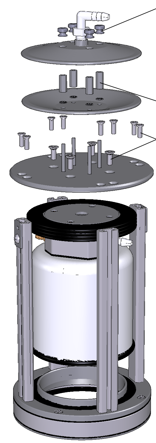
- Remove the four standoffs from the lower plate of the pressure vent.
- Remove the eight screws that attach the top plate to the chamber supports and the four screws near the center of the plate that attach to the top of the bellows.
- Note that the 4 screws nearest the center of the plate are slightly larger than the other 8 and have a small red o-ring seal on them. Make sure these o-rings are present and are not damaged when re-assembling the chamber. Replace if necessary.
- Now you can remove the bellows and chamber from the assembly.
- Note the orientation of the upper plate. There are screw inserts on the underside of this plate; it is important to re-insert this plate in the proper orientation during re-assembly. Note, too, that there is a thin film of silicone lubricant along the top edge of the bellows. This helps seal the bellows against the chamber top plate. There is a tube of silicone lubricant in the bellows kit that you can apply to the new bellows during re-assembly.
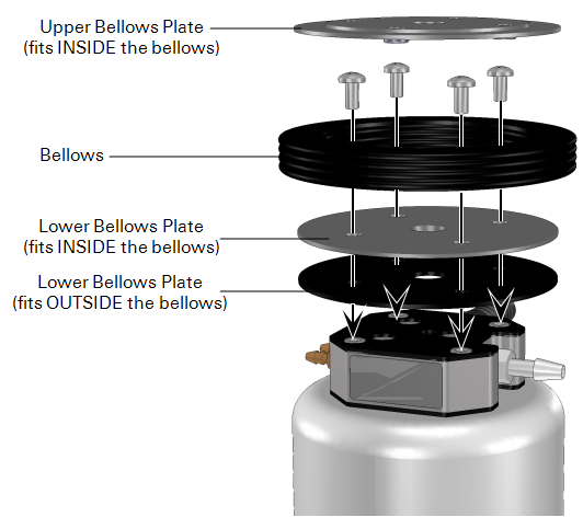
- Insert your finger between the bellows and the black plate and pry the plate out.
- There are two more plates at the bottom of the bellows. Remove the four screws from the base plates and remove the bellows.
- Note that there is a film of silicone lubricant applied to the bottom of the bellows, which helps seal it against the outer black plate. Remove the inner plate from the bellows, and discard the old bellows.
- To re-assemble the bellows, insert the lower black plate into the new bellows, by running your finger along the edge of the plate, as shown below.
- Apply a thin film of silicone lubricant around the edge of the bellows, and place the second black plate over the bellows.
- Align the holes between the two black plates.
- If the manifold gasket is torn or otherwise damaged, there are two spares in the spare parts kit. Align the bellows with two attached plates with the holes in the manifold (above). There is a seam on the bottom edge of the bellows. Before tightening the screws, align the seam in the bellows with one of the long edges of the manifold and attach with the four screws removed in Step 7 above. In other words, do not align the seam in the bellows with any of the corners of the manifold.
- Insert the black plate into the top of the bellows as shown.
- Note that the screw inserts should be on the underside of the plate. Apply a film of silicone lubricant around the top edge of the bellows. The screw inserts are on the underside of the top plate. They face downward, into the center of the bellows.
- If the chamber was removed earlier, re-insert it into the strut assembly.
- Make sure that the tubes are positioned between two of the struts with adequate clearance. Place the chamber top plate on top of the struts, align the screw holes, and secure the top plate to the struts with the eight screws.
- Attach the bellows to the chamber top plate.
- Lift up on the bottom of the chamber to compress the bellows to verify placement and clearances, and rotate slightly until the four screw holes on the chamber top plate and the bellows top plate align.
- Re-attach the lower plate from the pressure vent using the four standoffs with attached star washers.
- Attach the upper plate with the four thumbnuts. Re-attach the handle. Connect the chamber to the Analyzer Control Unit and manually open and close the chamber a few times to verify that there are no leaks.