
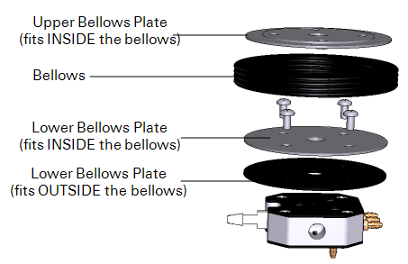
If the bellows on the 20 cm Survey Chamber is punctured or is otherwise damaged and develops a leak, it will not operate properly. If the chamber fails to raise or lower when the bellows pump is operating, the bellows and/or the Bev-a-line tubing on the bellows air path may be damaged. Check the Bev-a-line tubing first to see if it has developed a leak, and replace if necessary. If you have determined that the bellows is damaged, you can replace it using the optional bellows kit (part number 8100-623). Follow these steps to replace the 20 cm Survey Chamber bellows.
- Remove the four nuts from the bottom of the chamber supports.
- Gently move the supports out slightly to remove the bottom plate assembly.
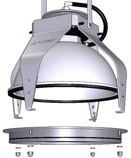
- Remove the four screws from the inside of the chamber, and remove the chamber bowl from between the chamber supports.
- This will expose the manifold and bellows assembly.
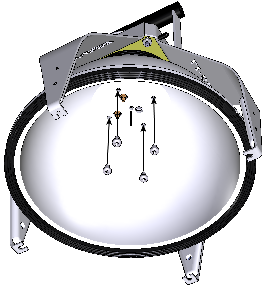
- Remove the four #10 Kep nuts in each corner of the bellows assembly with a 3/8" nut driver.
- Remove the four thumb screws from the top plate of the pressure vent assembly and lift the top plate off (optional).
- Remove the four screws from the bellows mounting plate.
- Note the orientation of the black plate at the top of the bellows - the screw inserts on the underside of this plate face down.
- There is a thin film of silicone lubricant along the top edge of the bellows. This helps seal the bellows against the bellows mounting plate.
- Insert your finger between the bellows and the first circular black plate and pry the plate out.
- There are two more plates at the bottom of the bellows.
- Remove the four screws from the two remaining circular base plates (inside the bellows) and remove the bellows from the manifold. Again, note that there is a film of silicone lubricant applied to the bottom of the bellows, which helps seal it against the outer black plate. Remove the inner plate from the bellows, and discard the old bellows.
- To re-assemble the bellows, insert the lower black plate into the new bellows, by running your finger along the edge of the plate.
- Apply a thin film of silicone lubricant around the edge of the bellows, and place the second black plate over the bellows.
- Align the holes between the two black plates. If the manifold gasket (below) is torn or otherwise damaged, there is a spare in the bellows kit.
- Align the bellows and two attached plates with the holes in the manifold.
- There is a seam on the bottom edge of the bellows. Before tightening the screws, align the seam in the bellows with one of the long edges of the manifold and attach with the four screws removed earlier. In other words, do not align the seam in the bellows with any of the corners of the manifold. Make sure that the bellows remains centered with respect to the two clamping plates.
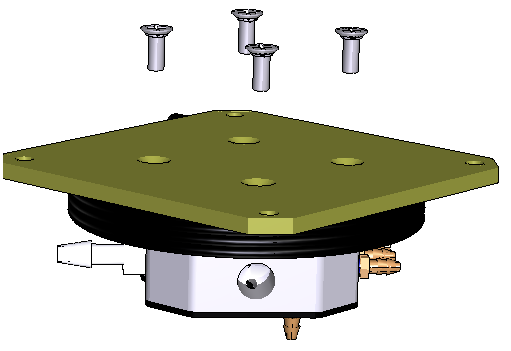
- Insert the remaining black plate into the top of the bellows.
- The screw inserts should be on the underside of the plate (inserts shown below). Apply a film of silicone lubricant around the top edge of the bellows.
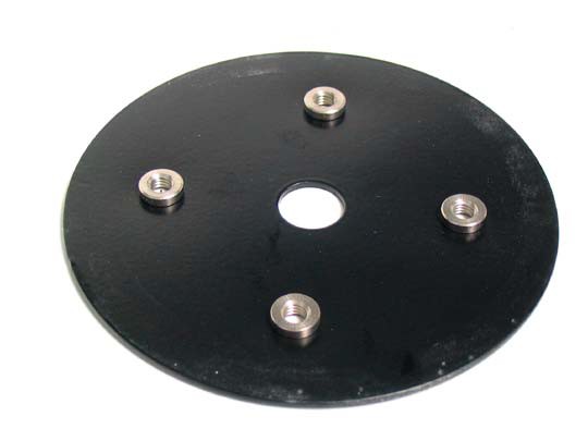
- The screw inserts are on the underside of the top plate, and face downward, into the center of the bellows.
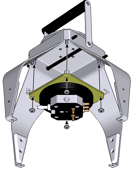
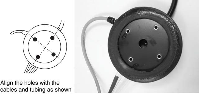
- Align the screw holes in the clamping plate with the tubing and control cables attached to the manifold, as shown below.
- Reattach the bellows mounting plate.
- Re-insert the bellows assembly into the support frame.
- Make sure that the plastic standoffs are still present on the four studs on the support frame. Note too that the gray control cable should extend around the outside of one of the support struts, as shown below.
- Re-attach the chamber bowl, making sure to insert the sensor wire through the small hole at the center of the bowl.
- Re-attach the bottom mounting plate with the four nuts removed earlier.
- Re-attach the top plate of the pressure vent using four thumb screws.