
The shaft seal assembly (part number 8100-928) has a recommended replacement cycle of three years. Replace the seal if the arm mechanism squeals or shudders during motion.
- With the chamber powered on, press the OPEN/CLOSE button twice in succession to move the chamber to its “Park” position. Disconnect the cable so the chamber is no longer powered.
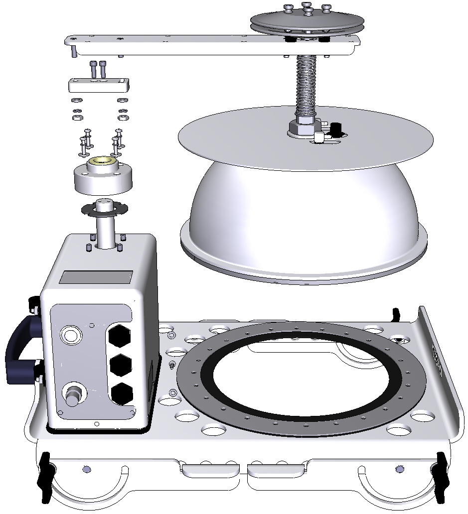
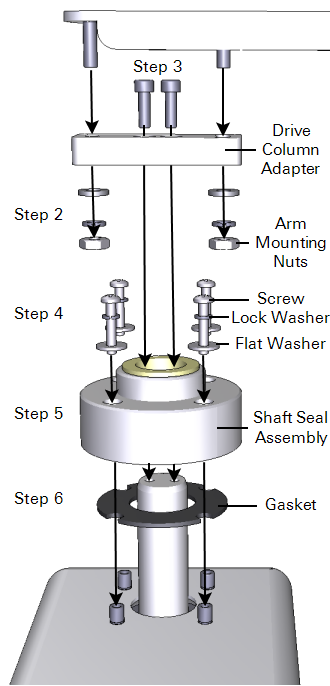
- Using a 3/8" socket, remove the arm mounting nuts on the underside of the arm that hold the bowl assembly.
- Remove the two hex screws on the drive column adapter using a 9/64” hex wrench.
- Remove the four screws and washers from the shaft seal assembly.
- Remove the shaft seal assembly from the drive column. It may be stuck on, so grasp it firmly and twist it loose.
- Replace the gasket (part number 6581-163). Begin by cleaning any residue off of the top of the housing. Use a mild detergent, if needed. Do not use sharp objects, and be careful not to damage the finish. Make sure the sealing surfaces are clean and smooth before installing the new gasket.
- Lubricate the new shaft seal assembly with oil and grease from the shaft seal assembly kit.
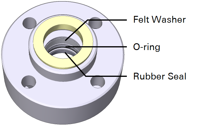
- Apply the full 1.5 ml of lubricant from the syringe to the felt washer inside the shaft seal assembly.
- With your finger or a cotton-tipped swab, apply a generous coat of grease to the O‑ring and rubber seal.
- Install the new shaft seal assembly on the shaft. You may need to press firmly and twist the assembly to get past the main shaft O-ring and seal, but use caution and be sure not to cut, pinch, or gouge the O-ring or seal. If the O-ring or seal is damaged, water may leak into the mechanism, causing damage.
- Apply a droplet of Loctite® (from the spares kit; part number 208-08233) to each of the four screws that were removed in Step 4, then install the screws, lock washers, and flat washers as shown in Figure 9‑3. Tighten the screws to 4 lb.-in.
- Important: Wipe any oil or grease off of the top of the shaft before installing the drive column adapter.
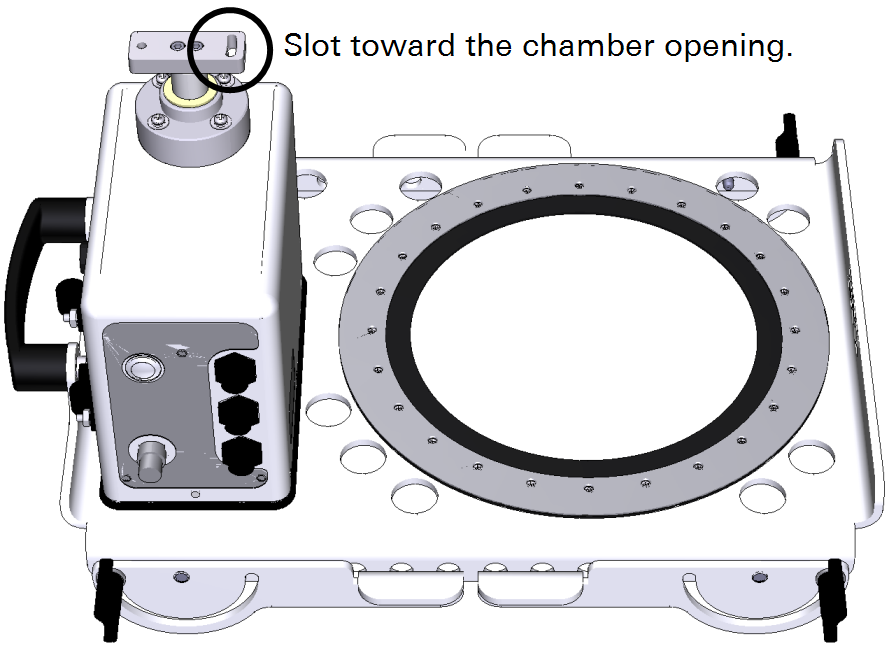
- Re-install the drive column adapter. The slotted side goes toward the chamber openining. Torque hex screws to 40 in-lbs.
- Re-install the bowl and arm assembly using the nuts and washers removed in Step 2.
- Tighten the nuts only finger tight, and then adjust the chamber bowl so that it is centered over the soil collar gasket.
- Tighten the two arm mounting nuts to 40 lb.-in.