
Connecting and Programming Soil Moisture Probes with the LI-8100A
Printable PDF: Connecting and Programming Soil Moisture Probes with the LI-8100A
This technical tip describes how to connect the EC-5 soil moisture probe from Decagon Devices to the LI-8100A. Includes programming instructions and a link to an optional calculation spreadsheet.
LI-COR offers two soil moisture probes for use with the LI-8100A Automated Soil CO2 Flux System. The ThetaProbe model ML2x (Delta-T Devices Ltd., Cambridge, UK) and the ECH2O model EC-5 (Decagon Devices, Inc., Pullman, WA, USA) both provide a voltage signal that corresponds to the volumetric water content of the soil. This value is a ratio, often expressed as θv = m3 H2O/m3 soil. Among other things, soil moisture can help explain the magnitude of soil CO2 fluxes measured with the LI-8100A system.
Connection to the LI-8100A System
There are two options for connecting a soil moisture probe. If the probe will be used with a single chamber and the LI-8100A, it must have bare wire leads in order to connect to a voltage port on the Auxiliary Sensor Interface (V1, V2, V3, or V4). If the probe will be used with a multiplexed system, it must have an 8-pin connector to attach directly to any port on an 8100-104 Long Term Chamber (V2, V3, or V4). The part numbers for these options are shown below.
| Part Number | Model | Connector | Connects to: |
|---|---|---|---|
| 8100-202 | EC-5 | Bare wire leads | Auxiliary Sensor Interface |
| 8150-202 | EC-5 | 8-pin connector | 8100-104 Long Term Chamber |
| 8100-204 | ML2x | Bare wire leads | Auxiliary Sensor Interface |
| 8150-204 | ML2x | 8-pin Connector | 8100-104 Long Term Chamber |
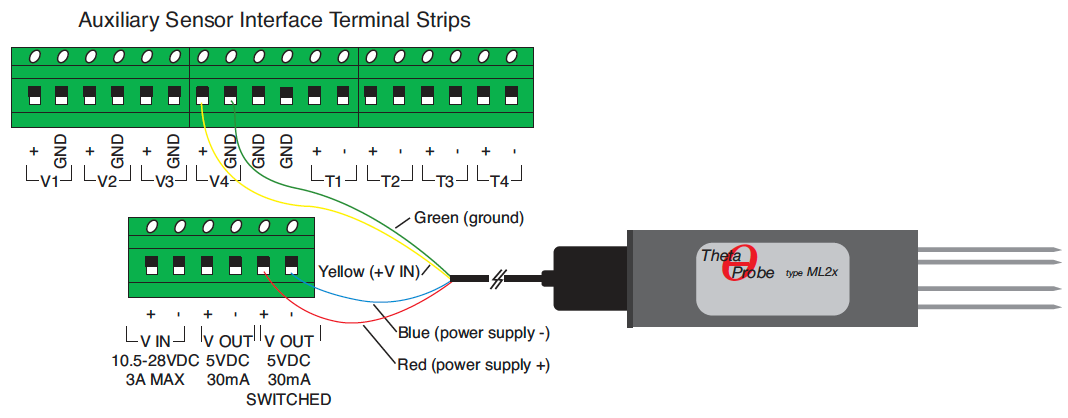
The 8100-204 ML2x soil moisture probe has four bare wire leads for connection to the Auxiliary Sensor Interface. Any one of the four voltage channels may be used; for demonstration purposes this document will use V4. The yellow wire should be connected to V4+, the green wire is connected to V4 GND, the red wire is connected to V OUT 5VDC SWITCHED+, and the blue wire is connected to V OUT 5VDC SWITCHED-.
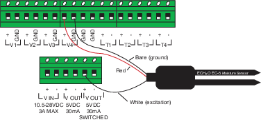
The 8100-202 EC-5 soil moisture probe has three wires. The red wire is connected to V4(+), the unshielded ground wire is connected to V4 GND, and the white wire is connected to V OUT 5 VDC.
Switched Excitation
Since continuous excitation may cause the sensor to exceed regulations on electromagnetic emissions, the LI-8100A provides an excitation voltage to the sensor in pulses. This excitation pulse is turned on for 10 seconds at a time to allow the sensor to stabilize before taking a sample. When a measurement is active, the soil moisture sampling occurs while the chamber is closing. When a measurement is not active, a sampling occurs once every 70 seconds. The data from that measurement are then kept until the next pulse, or until the next chamber measurement. The assumption is that the volumetric water content of the soil will not change drastically in that time.
Programming the LI-8100A for Soil Moisture Measurements
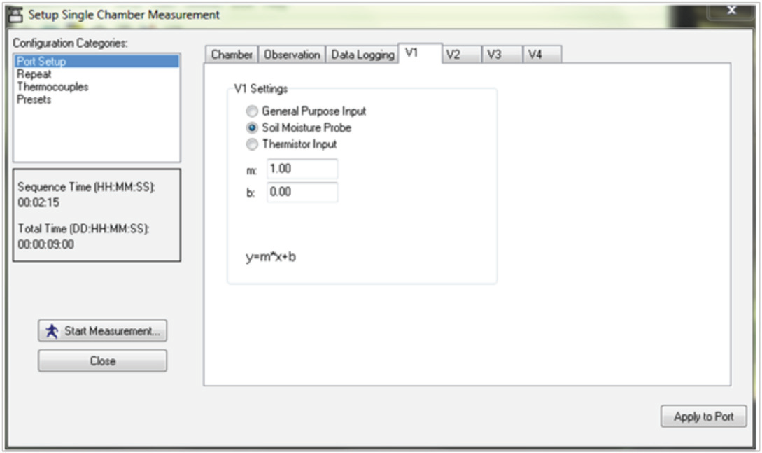
In the LI-8100A Windows® Application Software, the programming for the soil moisture probes will need to be configured. In the measurement setup, select one of the voltage input tabs (V1-V4 for single chamber measurements; V2-V4 with the multiplexer) that corresponds with your sensor. Select “Soil Moisture Probe” for this port. This will ensure switched excitation and a linear calibration.
The 8100-204 and 8150-204 ML2x probes have two generic linear calibrations, according to the percentage of organic matter content in the soil. The slope and offset can be entered directly into the LI-8100A programming. If a percentage is desired for volumetric water content, both the slope and offset can be multiplied by 100.
| Soil Type | Use for organic content: | Bulk density range (g cm-3) | Use for bulk densities: | Slope | Offset |
|---|---|---|---|---|---|
| Mineral | <7% | 1.25 to 1.5 g cm-3 | >1.0 g cm-3 | 0.53 | -0.06 |
| Orgainic | >7% | 0.2 to 0.7 g cm-3 | <1.0 g cm-3 | 0.58 | -0.03 |
The 8100-202 and 8150-202 EC-5 probes have a polynomial calibration when powered by a 5V excitation. This polynomial cannot be entered into the LI-8100A program, but the final values can be calculated in a spreadsheet after the data have been collected. For this reason, it is best to enter a slope of 1000 and an offset of 0. This will convert the sensor output into millivolts, which can later be used to calculate volumetric water content using this equation:
1‑1VWC = (-3.14E-07 * mV2) + (1.16E-03 * mV) – 6.12E-01
It is also possible to perform a soil-specific calibration of either probe to obtain a more accurate equation. Refer to the original manufacturers (Delta-T Devices or Decagon Devices) for more information.