
Using an ML3 Soil Moisture and Temperature Probe
Printable PDF: Using an ML3 Soil Moisture and Temperature Probe
(8100A_ML3_TTP62.pdf)
Download this content as a pdf that can be saved to your computer or printed.
Soil moisture and temperature measurements can help explain the magnitude of soil CO2 fluxes measured with the LI-8100A Automated Soil CO2 Flux System. LI-COR sells the Decagon GS1 soil moisture sensor as part number 8100-205 and 8150-205, and soil temperature sensors as part numbers 8100-203 and 8150-203. The LI-8100A can convert the voltage signals from these sensors into soil moisture and temperature in real time.
A ThetaProbe model ML3 (Delta-T Devices Ltd., Cambridge, UK) can instead be used to measure soil moisture and soil temperature simultaneously. It can be connected to the LI-8100A through the 8100-663 Auxiliary Sensor Interface. Alternatively, it can be connected to the 8100-104/C long term chambers when using an LI-8150 multiplexer. However, the data analysis requires more extensive calculations than the standalone soil moisture or soil temperature sensors.
Connection to the LI-8100A single-chamber system
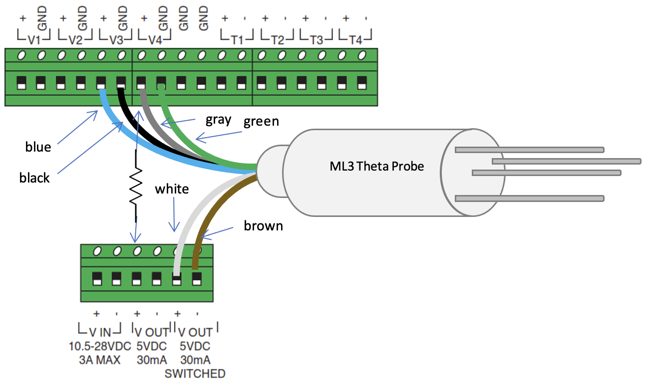
| ML3 Wire Color | Purpose | Terminal |
|---|---|---|
| White | Power | V OUT 5VDC 30 mA SWITCHED (+) |
| Brown | Power Ground | V OUT 5VDC 30 mA SWITCHED (-) |
| Blue | Soil Moisture Signal + | V3 (+) |
| Black | Soil Moisture Signal - | V3 (GND) |
| Gray | Temperature Signal + | V4 (+) |
| Green | Shield | V4 (GND) |
In addition, a resistor should be connected between V4 (+) and V OUT 5VDC 30 mA SWITCHED (+). The resistor should have a known value near 10 Kohm, and should have a 1% or better tolerance. This can be purchased from LI-COR as part number 471-01007.
Connection to the LI-8100A multiplexed system
The ML3 should be connected to two 392-08577 cables, available from LI-COR. These connectorized cables can connect to the V3 and V4 ports on the 8100-104 chambers when used with a multiplexer. The wires can be soldered or connected through a junction box or other watertight enclosure.
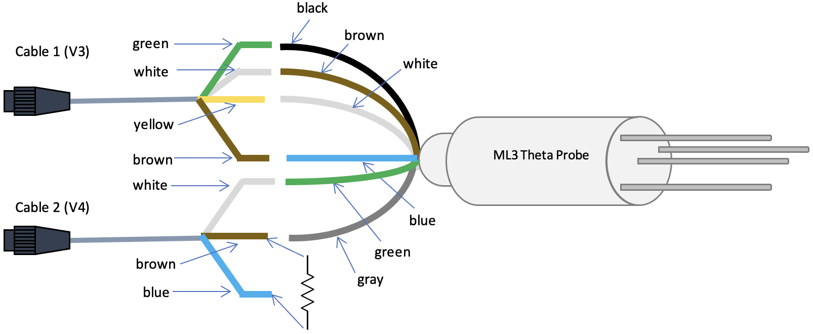
| ML3 Wire Color | Purpose | 392-08577 (1) Wire Color |
392-08577 (2) Wire Color |
|---|---|---|---|
| White | Power | Yellow | |
| Brown | Power Ground | White | |
| Blue | Soil Moisture Signal + | Brown | |
| Black | Soil Moisture Signal - | Green | |
| Gray | Temperature Signal + | Brown | |
| Green | Shield | White |
In addition, on the second cable, a resistor should be connected between the blue and brown wires. The resistor should have a known value near 10 Kohm, and should have a 1% or better tolerance. This can be purchased from LI-COR as part number 471-01007.
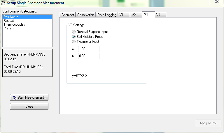
Programming the LI-8100A for measurements
Connect to the LI-8100A using its Windows Interface software. Under Setup, Chamber Configuration, select the V3 tab to configure the soil moisture measurement. Select Soil Moisture Probe as the input, and leave m=1.00 and b=0.00 so that V3 will record the sensor output in volts.
Go to the V4 tab to configure the soil temperature measurement. Select Thermistor Input, and set A=0, B=0.001, and C=0.
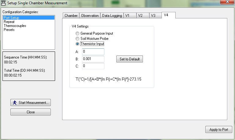
Under the Data Logging tab, make sure that V3 and V4 are both selected.
Soil moisture calculations
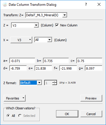
For the soil moisture calculation, open the .81x data file in SoilFluxPro Software (available for free download). Click on the Transform button at the top (or Edit, Column, Transform).

A new dialog window will appear. Select Z = DeltaT_ML3_Mineral(X) or DeltaT_ML3_Organic(X), depending on the soil type. Select Z = New Column, to create a new column in the data file. Select X = V3, and All data. Make sure that you select All observations. The default coefficients will be populated according to the polynomials provided by Delta-T for generalized soils:
1

2

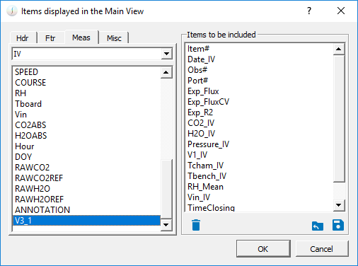
Soil moisture will appear in a new column, labeled V3_1. You can click on the Display button to add it to the displayed values (it is under the Meas tab). You can also save the data file.
Soil temperature calculations
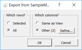
The soil temperature calculation must be performed in a separate software, like Microsoft Excel. We would recommend opening the data in Soil Flux Pro, then click on the Export button at the top (or File, Export).

A new window will appear. Click on All rows, and select Other columns.
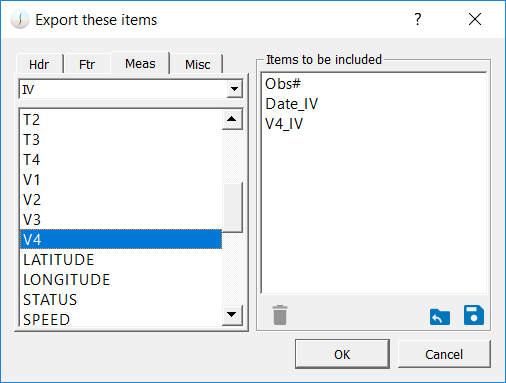
Click on Define to select which variables are exported. Under the Hdr tab, click and drag Obs# to the right side of the window. Click on the Meas tab and click and drag Date and V4 as well. You can add other variables if you want, and delete any other variables in the right side of the window.
You can then save this file or copy it to the clipboard, and paste it in an Excel file or text file. From the V4 value, you will need to calculate the measured resistance Rmeas.
3

In Excel, this would be =EXP(1/(0.001*(C2+273.15))), assuming C2 is the first V4 value.
From the measured resistance, you will calculate the thermistor resistance R.
4

where Rc is the resistance of the cable (0.066 ohms per meter, therefore 0.33 ohms for standard 5 m cable), and Rref is the resistance of your added resistor between V4 and the excitation channel, which should be somewhere around 10000 ohms. The thermistor resistance R is in units of Kohms. In Excel, this would be = (-0.0036*0.33*(10000 + D2)) + D2, assuming D2 is the first Rmeas value.
You can then interpolate the temperature from the following lookup table published by Delta-T. A reasonable approximation of this lookup table is:
5

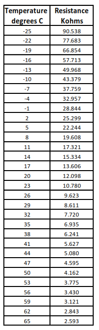
Source: User Manual for the ML3 ThetaProbe, ML3-UM-1.0, Delta-T Devices Ltd.