
 The following example shows how you can connect the LI-820 to a datalogging device such as the LI-COR Model LI-1400 DataLogger to collect analog data and convert to meaningful CO2 values. The CO2 concentration is calculated from the DAC output voltage as follows:
3‑8

where V is the measured voltage, XF is the full scale value for CO2 output (entered in the Settings Window as the 2.5 or 5 V full scale value, up to 20,000 ppm), XZ is the zero value entered, and Vmax is the full scale DAC output voltage selected (5 V or 2.5 V).
For example, if the voltage range selected is 0-5 V (Vmax), the zero CO2 value entered is 0 ppm (XZ), the full scale CO2 value entered is 2000 ppm (XF), and the measured output voltage (V) is 2.9 V, the equation would take the form
3‑9

= 1160 ppm.
This general equation can be converted into simple multipliers, based on the two available voltage output ranges, and the CO2 range (maximum 20,000, but can be any value, depending on what is chosen for the 0 V and full scale 2.5 V or 5 V DAC output values). This multiplier can then be entered in the data logging device to convert raw voltage to CO2 values. Table 3‑1 lists some examples of values for this multiplier; simply choose the DAC output range in the second row, and then select the LI-820 CO2 range in the first column (the full scale value minus the zero value); follow across to find the appropriate multiplier. Note that this table assumes that the zero value (XZ) is zero; if it is not zero, the offset will need to be added onto the final result.
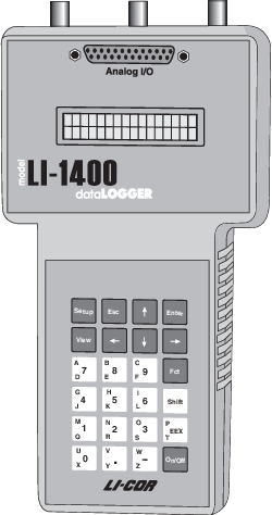
The LI-1400 can be used to monitor voltage signals up to 2.5 volts with 76 microvolt resolution in real time and convert them into meaningful engineering units shown on the display. Alternatively, the LI-1400 can be configured to automatically log these data over extended periods of time and later dump the results to a computer for further analysis.
Access to the voltage channels requires the 1400-301 Terminal block. Voltage channels are designated by the letter “V” and sequentially numbered V1-4. The lead from LI-820 terminal #7 or #9 should be attached to one of the LI-1400 terminals labeled V1, V2, V3, or V4, while the lead from terminal #8 or #10 should be attached to one of the LI-1400 terminals labeled t.
The following example shows how you can set up the LI-1400 Data Logger to collect raw voltage output from the LI-820 and convert to CO2 values.
- Set the voltage output of the LI-820 for 2.5V output as described in Section 3, Analog Output.
- In the LI-1400, configure V1 channel as General for CO2.
- Enter a description, such as CO2.
- Set Math = Poly(nomial) and press Ent(er).
- Set description as desired, a1 = multiplier from Table 3‑1, a0, a2-a5 = 0. When finished, press Esc to return to the main configuration list.
- Set Oper(ator) = none.
- Enter a Label such as ppm for the units.
- Set Average=1 sec or as desired. CO2 will now be displayed on channel V1. To log CO2 automatically, follow the remaining steps:
- Set Log Routine to the desired log routine.
- Set Calc=Mean.
- To capture the minimum and maximum CO2 values, set MinMax accordingly.
- TCoef has no effect when Calc=Mean. It is used only when integrating.