
Theory of Operation
System Overview
The instrument uses digital signal processing techniques to determine the temperature and pressure corrected CO2 concentration based on the optical bench signals through the use of a ratio technique. The data are passed through a calibration function that performs linearization of the detector signal to a mole fraction mixing ratio of CO2 in air given in μmol CO2 per mole of air, or ppm (see Computing CO2 Mole Fraction below).
Optical Bench System
Data output is provided in a digital format through an RS-232 interface that supports connection to an external computer. The instrument comes with a Windows-compatible application for instrument configuration, control, data collection and display. Analog signals are available through a terminal block for collection by a data logger or similar means.
The LI-820 CO2 Gas Analyzer optical path is a thermostatically controlled IR detection system. The optical bench operation is based upon a broad band IR source and two pyroelectric detectors. The source is mounted in a parabolic reflector to collimate the light and increase energy through the optical path to the detectors. The reflector and optical path are gold plated to further increase energy transmission. The detectors are pyroelectric devices that operate based on thermal energy received. The narrow band optical filters allow only the two wavelengths of interest to illuminate a detector, allowing for the determination of CO2 concentration in the presence of other infrared absorbing gases such as water vapor.
The detectors respond to thermal energy, so it is necessary to precisely regulate the detectors’ temperature. This allows for differentiation of thermal gradient noise from the received signals from the optical path. The detection subsystem is shown in Figure 4‑1.
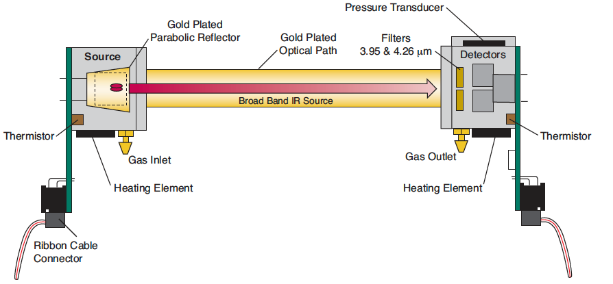
The optical bench has a thermostat that maintains a constant operating temperature of 50 °C. A feedback loop is used to regulate the optical bench temperature. As shown in Figure 4‑1, two thermistors, located in the source and detector housings, measure the present temperature. The thermistors are monitored as part of the control loop to determine corrections necessary in the thermal balance. Two heating elements are the sources of thermal energy into the source and detector housing. The optical path is in mechanical contact with the source and detector housing and thereby achieves thermal equilibrium.
The bench requires approximately 10 minutes to achieve the specified thermal temperature. A longer period of approximately 1.5 hours is required to bring the performance of the detection system to within 1 to 2% of reading. As shown in Figure 4‑1, the detector housing has a pressure transducer integrated into the housing design. Part of the CO2 concentration calculation depends on the pressure observed in the optical path, measured with an in-line pressure transducer. Many parameters can affect the pressure and thus the concentration reading. The processing center in the analyzer reads the pressure reading as part of its data collection task and uses this information in the concentration calculation. The gas flow enters the source housing, passes down the optical path and exits at the detector housing. The maximum flow rate for the analyzer is approximately 1 liter/min.
Another key parameter in the concentration calculation is the gas temperature in the optical path. It is assumed in the analyzer operation that the gas temperature will equilibrate to the optical bench temperature (50 °C) by the time it enters the optical path. Since the instrument performs temperature and pressure corrections as part of the concentration calculation, this assumption is very important. To cause the sample air to equilibrate to the optical bench temperature, an airflow pattern is created with sufficient eddy currents to cause thermal equilibration.