User-Built Systems
Authors: LI-COR, Inc.
Correspondence: envsupport@licor.com
Instruments: LI-8250
Keywords: soil chamber, custom, control kit
Abstract
The 8200-104 Opaque Long-Term Chamber and 8200-104C Clear Long-Term Chamber are closed-transient chambers built for long-term field deployment. Researchers typically use these chambers in an LI-8250 Multiplexer system. The multiplexer manages gas flow, controls operation, and collects data from chambers and their auxiliary sensors. However, there may be applications where you would like to use the 8200-104/C long-term chambers with a user-built controller or manifold system. In this case, you must develop the system to control the chamber, collect the data, and process the data. This application note details how to power and communicate with the 8200-104/C chambers. You can find more information about installing the chambers in the field and connecting sensors in the LI-8250 Instruction Manual.
1 | Chamber control kit
LI-COR provides a kit with the necessary components to interface a user-built controller with an 8200-104/C long-term chamber for standalone applications. The Chamber Control Kit (part number 8200-401) enables you to interface with one 8200-104/C long-term chamber. Each 8200-104/C long-term chamber will require its own kit (see Table 1).
2 | Pneumatics
The 8200-104/C long-term chambers and the cable assembly (part number 9982-056) use quick-connect fittings to attach pneumatic lines. On the chamber or the controller end of the cable assembly, the quick-connect receptacle provides airflow to the chamber (see Table 1).
For reference, the flow rate through the chamber provided by the LI-8250 Multiplexer and the cable assembly is ~2.8 SLPM. For a smooth surface under the chamber, good mixing is expected at flow rates down to 1.7 SLPM. Below that flow rate, good mixing is not guaranteed.
3 | Power
The chamber requires a nominal 24 VDC power supply. If input voltage goes below 17 VDC, the chamber will report a power supply error, and below 14.5 VDC, the chamber will shut down. If input voltage goes above 28 VDC, it will damage the chamber electronics. Note that these voltages are specified as supplied at the chamber. When using the LI-COR cable assembly, there will be some resistance (2.4 to 2.8 ohms) which will result in a small voltage drop.
The nominal power draw by the chamber is ~0.4 watts when the chamber is not moving. During normal chamber movement, power demand will increase to about 7.5 watts. If chamber movement is obstructed, power demand will peak at 24 watts and will cycle between ~0 and 24 watts over 2 to 3 seconds.
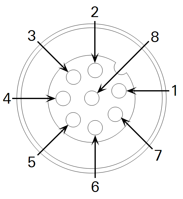
To connect the combined power and data cable between the chamber and system controller, connect the bare leads from the 8-pin bulkhead adapter (part number 310-16700) to the terminals on the controller (see Table 2). Connect the bulkhead adapter to the 15-meter cable (part number 9982-056), then connect the cable to the chamber.

4 | Serial interface
The chamber uses full-duplex RS-422 operating at 115,200 baud to communicate with a controller. Few off-the-shelf platforms typically used in user-built controllers offer native hardware support for RS-422. For these platforms, you will need an adapter to convert between RS-422 and a supported hardware communication interface.
There are several such adapters available through third-party suppliers that you can use to convert RS-422 to RS-232, USB, or TTL. We have tested adapters from CommFront (commfront.com) and Zihatec (hwhardsoft.de) and verified compatibility with the chamber. See Table 3 and Table 4 for configuration and wiring of the Zihatec adapters.
For those interfacing to platforms such as Arduino or Raspberry Pi, an RS-422 to TTL adapter is recommended. The TTL output from the adapter should be connected to a physical serial UART on these devices. Note that for Arduino specifically, the software emulated serial ports (such as those provided by the AltSoftSerial library) are not fast enough at the chamber’s baud rate, leading to message corruption. For making a TTL connection to the platform’s serial port, be mindful of the TTL voltage levels supplied by the adapter. Raspberry Pi, for example, only supports a 3.3 VDC maximum input on its GPIO pins, whereas many TTL devices will output a maximum of 5 VDC.
For those interfacing to a computer or other device via USB, a flying lead RS-422 to USB adapter is available from LI-COR (part number 392-16348). Connections for the USB adapter to the 310-16700 bulkhead are in Table 5.
5 | Messaging
Messages sent between a user-built controller and an 8200-104/C chamber have a five-part structure. Each message begins with an origin identifier, followed by a sequence number, checksum, and JSON object. All messages are terminated with a newline character (ASCII 10).

5.1 | Origin
The origin defines the source of the message. For messages originating from an 8200-104/C chamber, the origin will always be null (""). If the message relates to an SDI-12 sensor connected to the chamber, the origin will be the sensor’s SDI-12 address. Note that allowable SDI-12 addresses are restricted to 0 through 9 for an 8200-104/C chamber.
5.2 | Sequence
The sequence is an integer (-1 or 1 to 32767) used to track messages. For each message received with a sequence number greater than zero, an acknowledgment should be returned by the receiving device. For the example above sent by an 8200-104/C chamber, the controller would respond with:
"" 239 -1 "{"ack":""}"This acknowledges receipt of message 239 from the chamber. For messages using a sequence of -1, no acknowledgment is expected. For most messages initiated by the controller, it is okay to use a sequence number of -1, as most of these elicit some response message from the chamber, negating the need for the chamber to send a separate acknowledgment message.
5.3 | Checksum
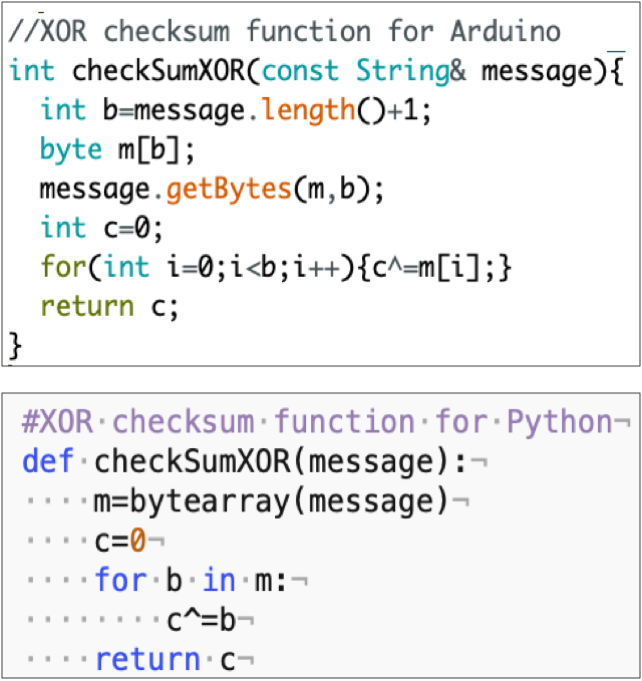
The checksum is a bitwise XOR of the JSON object. For acknowledged messages, it should always be included. The checksum is calculated by the receiving device (controller or chamber) and compared to the checksum in the original message. This ensures the message has not been corrupted. For acknowledged messages where the checksums do not match, a non-acknowledgment would be sent:
"" 239 -1 "{"nak":""}"Example functions for computing the checksum using Python and the Arduino IDE are given in Figure 3. These functions accept the JSON object as a string and return the checksum as an integer value.
5.4 | JSON object
The JSON object contains the data items passed between the chamber and controller. Each data item is composed of a key:value pair. 8200-104/C chambers support a wide array of communication and configuration objects.
Tools exist in Python and the Arduino IDE for constructing and parsing JSON objects. For Python, manipulation of JSON is included in the standard JSON library. For the Arduino IDE, the third-party library ArduinoJson (arduinojson.org) provides a very efficient implementation.
Both environments also provide built-in functions for serial communication. The examples below show how to:
- Deserialize JSON in the respective environments
- Issue an identity request
- Parse the contents of the response message
The examples in Listing 1 and Listing 2 show how to serialize and deserialize JSON in both environments and how to publish a response to an identity request.
Note: The code for these scripts may be copied from the listings below or may be downloaded from licor.app.boxenterprise.net/s/utw5f12b93wo8d59y7zebjlk90qpvg5n.
Listing 1. An example Python script.
#Example Python script for requesting and parsing chamber identity
import json
import serial
import time
ser=serial.Serial('/dev/serial0', 115200)
#XOR checksum function for Python
def checkSumXOR(message):
m=bytearray(message,'utf-8')
c=0
for b in m:
c^=b
return c
#Example function for parsing a message
#Returns a dictionary containing the contents of the json object
def messageParser(message):
try:
#Origin=osc[0], sequence=osc[1], checksum=osc[2]
osc=message[:message.find('"{')].split(' ')
object=message[message.find('{'):-2]
#Validate the checksum and send an acknowledgement if they match
if int(osc[2]) is not -1:
ack='nak'
if checkSumXOR(object)==int(osc[2]):
ack='ack'
ser.write(bytes('"" '+str(osc[1])+' -1 "{"'+ack+'":""}"\n','utf-8'))
return json.loads(object)
except:
return {'message':'error'}
tlast=0
while True:
tnow=time.time()
if ser.inWaiting()>0:
print (messageParser(ser.readline().decode('utf-8')))
#Request an identity message every 5 seconds
if tnow-tlast>=5:
tlast=tnow
ser.write(bytes('"" -1 -1 "{"identify":""}"\n','utf-8'))Note that in the Arduino IDE example, the choice to declare the buffers for working with the JSON objects inside a function separate from the main loop is deliberate and stems from how these buffers are handled by ArduinoJson. Refer to the library’s documentation for more details.
Listing 2. An example Arduino IDE script.
//Example Arduino script for requesting and parsing chamber identity
#include "ArduinoJson-v5.13.3.h"
int checkSumXOR(const String& message){
int b=message.length()+1;
byte m[b];
message.getBytes(m,b);
int c=0;
for(int i=0;i<b;i++){c^=m[i];}
return c;
}
//Example function for parsing a message
bool messageParser(const String& message){
bool type=false;
//Parse the origin (-1 for null orgins), sequence number, and checksum
int origin=-1;
if(message.charAt(1)!="\""){origin=int(message.charAt(1));}
int sequence = message.substring(message.indexOf("\" ")+2,message.indexOf(" ",message.indexOf("\" ")+2)).toInt();
int checksum = message.substring(message.indexOf(" ",message.indexOf("\" ")+2),message.lastIndexOf(" {")).toInt();
//Validate the checksum and send an acknowledgement if they match
if(checksum!=-1){
String ack="nak";
if(checksum==checkSumXOR(message.substring(message.indexOf("{")-1,message.lastIndexOf("}")+2))){ack="ack";}
Serial.println("\"\" "+String(sequence)+" -1 \"{\""+ack+"\":\"\"}\"");
}
StaticJsonBuffer<150> recieveBuffer;
JsonObject& chamber_json = recieveBuffer.parseObject(message.substring(message.indexOf("{"),message.lastIndexOf("}")+1));
if(chamber_json.success()){
type=true;
if(chamber_json.containsKey("identity")){
String id_type=chamber_json["identity"]["type"]; //Gets type from an identity object
}
if(chamber_json.containsKey("chamber_status")){
String chamber_status=chamber_json["chamber_status"]; //Gets chamber state from an chamber_status object
}
}
recieveBuffer.clear();
return type;
}
void setup() {
Serial.begin(115200);
}
int tlast=0;
void loop() {
int tnow=millis();
if(Serial.available()){messageParser(Serial.readStringUntil('\n'));}
//Request an identity message every 5 seconds
if((tnow-tlast)>=5000){
tlast=tnow;
Serial.println("\"\" -1 -1 \"{\"identify\":\"\"}\"");
}
}6 | Commands
There are many commands you can use to interface with the 8200-104/C long-term chambers and connected devices.
6.1 | Identify
An identify command asks the chamber to identify itself and any connected SDI-12 sensors. The controller should always use a sequence number of -1 for these messages. In response, the chamber will send one or more identity objects. The chamber may also send error objects if any SDI-12 sensors use an address outside 0 through 9. A chamber_status will also be sent in response. To query for an identity, the controller sends:
"" -1 -1 "{"identify":""}"Here are some example responses from the chamber:
"" 1 88 "{"identity":{"type":"ltc","model":"8200-104","sn":"82L-0198","sver":"0.0.78","hver":"2"}}""0" 2 9 "{"identity":{"type":"sdi-12","model":"STEVENSW-093640","sn":"ST4SN00256922","sver":"2.9","hver":"12"}}""" 3 125 "{"chamber_status":"closed","type":"ltc","sn":"82L-0198","diag_code":0}"When a previously identified SDI-12 sensor is removed, the chamber will send an unsolicited device_removed message with the origin corresponding to the sensor’s address.
Here is an example message for a removed SDI-12 sensor:
"0" 4 109 "{"device_removed":{"type":"sdi-12"}}"6.2 | Chamber
A chamber command is used to tell the chamber to open, close, or park. To close the chamber, for example, the controller sends:
"" -1 -1 "{"chamber":"close"}"The chamber will respond to a chamber command with one or more chamber_status objects indicating its current position or motion (i.e., closing, closed, opening, open, parking, parked, manual_move, or unknown). The chamber also sends these objects whenever it starts or stops a move operation. An unknown state will be reported immediately after powering on (before any move operation has occurred) and after a motor stall.
Here is an example chamber_status message:
"" 1 28 "{"chamber_status":"closing","type":"ltc","sn":"82L-0198","diag_code":0}"6.3 | Measurement
A measurement command tells the chamber to start or stop sending data. Once in measurement mode, the chamber will stream chamber data once per second and SDI-12 sensor data every time it is read. The measurement rate of SDI-12 sensors depends upon the min_interval setting in the SDI-12 configuration. To start measurement mode, the controller sends:
"" -1 -1 "{"measurement":"start"}"Here is an example of the type of data the chamber will return:
"" 1 13 "{"data":{"voltage_in":24.18,"motor_current":0.00,"board_temp":24.55,"temperature":21.77,"light":-1},"source":{"type":"ltc","sn":"82L-0198"}"diag_code":0}"6.4 | Configuration
A config command allows the controller to set the chamber open position and parameters related to auxiliary sensors. Each sensor has a default measurement configuration it will use unless overwritten by a config command.
The chamber will respond with a config_response after every config command. The response indicates if the configuration was successful or if it failed and includes any error messages.
Here is an example response to a successful config:
"" 1 9 "{"config_response":"success"}"6.4.1 | Chamber open position
The chamber_open_position command configures the open position using a value from 0 to 180 degrees. Multiples of 30 degrees are expected, but not required. The closest possible position to the requested position will be used, but an exact representation is not possible in many cases. This value is stored in non-volatile memory.
"" -1 -1 "{"config":{"chamber_open_position":120}}"6.4.2 | Remove all sensors
The remove_all_sensors command removes all SDI-12 sensor information on the chamber and restores the default sensor configuration.
"" -1 -1 "{"config":{"remove_all_sensors":""}}"6.4.3 | Light
The light command sets the light sensor type (LI-190R or LI-200R) and calibration multiplier for a light sensor connected to the chamber.
"" -1 -1 "{"config":{"light":{"type":"LI-190R","multiplier":-112.2}}}"6.4.4 | Config SDI-12
The sdi-12 command sets information for one SDI-12 sensor connected to the chamber. The range for the address field is 0 through 9, inclusive. The min_interval value is the sampling interval (in seconds) for the sensor. Consult the manufacturer's documentation to choose an appropriate interval for the sensor. The command value defines the SDI-12 sensor measurement set.
The fields value defines what parameters from the measurement set are returned with sensor data from the chamber. The fields value is an array with the position(s) of the desired parameter(s) from the measurement set. Sending an empty array tells the chamber to return the complete measurement set. If the chamber receives a configure command using the same address as was used on a previous sensor, the new configuration will replace the existing one.
Here are some example configurations for SDI-12 sensors:
"" -1 -1 "{"config":{"sdi-12":{"address":"8","min_interval":60,"command":"M2","fields":[0,2]}}}""" -1 -1 "{"config":{"sdi-12":{"address":"0","min_interval":15,"command":"M","fields":[0,1,2,8]}}}""" -1 -1 "{"config":{"sdi-12":{"address":"1","min_interval":60,"command":"M","fields":[]}}}"6.5 | Query Configuration
A query_config command queries the chamber for its current configuration. The chamber responds with one or more messages containing a config_data object. If the related configuration is not set or empty, the config_data object will contain a null string.
6.5.1 | Chamber open position
The chamber_open_position query requests the chamber open position. The controller sends:
"" -1 -1 "{"query_config":"chamber_open_position"}"The chamber responds with the current chamber open position:
"" 1 9 "{"config_data":{"chamber_open_position":120}}"6.5.2 | LTC sensors
The ltc_sensors query requests the configuration of the air temperature and light sensor settings. The controller sends:
"" -1 -1 "{"query_config":"ltc_sensors"}"Here are two example responses from the chamber:
"" 1 121 "{"config_data":{"light":{"type":"LI-190R","multiplier":-2912.2}}}""" 2 41 "{"config_data":{"temperature":""}}"6.5.3 | Query config SDI-12
The sdi-12 query requests the configuration of all connected SDI-12 sensors. The controller sends:
"" -1 -1 "{"query_config":"sdi-12"}"The chamber responds with one message, similar to the example below, for each configured SDI-12 sensor.
"" 1 84 "{"config_data":{"sdi-12":{"address":"0","min_interval":60,"command":"M","fields":[0,1,2,7,8]}}}"6.5.4 | Serial number
The serial_number query requests the chamber serial number. The controller sends:
"" -1 -1 "{"query_config":"serial_number"}"Here is an example response from the chamber:
"" 1 114 "{"config_data":{"serial_number":"82L-0198"}}"6.5.5 | Model number
The model_number query requests the chamber model number. The controller sends:
"" -1 -1 "{"query_config":"model_number"}"Here is an example response from the chamber:
"" 1 100 "{"config_data":{"model_number":"8200-104"}}"6.6 | State
A state command is used to modify the enabled state of a given sensor by sending a state of enable or disable. By default, the light and chamber temperature sensors are enabled and SDI-12 sensors are disabled. The chamber responds with a state_response of success for a valid state command or with an error in the case of an unrecognized or invalid command:
"" 1 116 "{"state_response":"success"}"Here are example commands to enable the light and chamber temperature sensors :
"" -1 -1 "{"state":"enable","light":""}""" -1 -1 "{"state":"enable","temperature":""}"To enable an SDI-12 sensor, include the sensors address as the value for the sdi-12 key:
"" -1 -1 "{"state":"enable","sdi-12":"2"}"6.7 | SDI-12
Here the sdi-12 command sets the chamber to transparent mode. This allows any arbitrary command to be passed to the SDI-12 bus to report back the full bus response. If no response is received from the bus, the chamber responds with an error. Transparent commands will not be handled if the chamber is in measurement mode. The maximum allowed length of the SDI-12 command is 15 characters. For example:
"" -1 -1 "{"sdi-12":"0D0!"}"If an SDI-12 sensor is connected to the chamber with address 0, the chamber forwards the sensor’s response to D0 in an sdi-12_rsp object:
"" -1 -1 "{"sdi-12_rsp":"0+0.000+0.002+23.9","code":""}"7 | Errors
Errors are sent when an error state occurs. Errors can be associated with one of the previously described commands or encountered by the chamber unassociated with any request from the controller.
The error type provides the general type for the error that occurred, and detail provides a text description of the error. The type will have one of the following values: message, motor, eeprom, sdi-12, light, temperature, board_temp, voltage_in.
SDI-12 errors include the sensor address (addr) where the error occurred. Motor errors include a move_stats object with details about the motor operation and power supply when the error occurred. All error messages include a diagnostic code (diag_code) analogous to that provided with chamber_status.
Here are some example error messages:
"" 1 69 "{"error":{"type":"temperature","detail":"Thermistor open"},"diag_code":33}""" 2 38 "{"error":{"type":"sdi-12","addr":"Z","detail":"Detected SDI-12 device (STEVENSW 000001, ST3SN00253634) with out-of-range address"},"diag_code":8}""" 3 76 "{"error":{"type":"voltage_in","detail":"Input Voltage low: 19.6"},"diag_code":136}""" 3 76 "{"error":{"type":"voltage_in","detail":"Input Voltage low: 19.6"},"diag_code":136}""" 4 48 "{"error":{"type":"motor","detail":"Motor Stall"},"diag_code":138,"move_stats": {"movement":"opening","motor_current_ave":0.74,"motor_current_max":2.53,"voltage_in_ave":23.70,"voltage_in_min":22.53,"motor_ms":14754}}""" 5 63 "{"error":{"type":"sdi-12","addr":"1","detail":"Device not detected"},"diag_code":8}"8 | Diagnostic Code
The diag_code object is a bit field to identify errors. A diagnostic value of 0 indicates normal operation. Other values indicate an error. The bits in Table 6 are those used by the 8200-104/C Long-Term Chambers. For fatal errors that cause the chamber to reboot, the error flag will remain set until the chamber is power cycled. All other errors are cleared after rebooting.
9 | Resources
The resources below can provide you with more details about using your 8200-104/C Long-Term Chamber.
-
LI-8250 Multiplexer manual: licor.com/8250manual
-
LI-8250 Multiplexer support: licor.com/8250support
-
Support: licor.com/support