Performing the leak tests
With the large amount of tubing and connections in a multiplexed system, leaks may develop over time. This is especially true as the system ages. Fortunately, it is relatively easy to check for any leaks using the System Leak Test and to narrow down where the leak is with the Component Leak Test. If the system has been modified to measure samples in flasks, additional steps are described in Leak testing systems configured for flask measurements.
System leak test
Follow this procedure to perform a System Leak Test on an LI-8250 Multiplexer, either with or without the 8250-01 Extension Manifold. If you have configured the system for flask measurements, read Leak testing systems configured for flask measurements for important considerations.
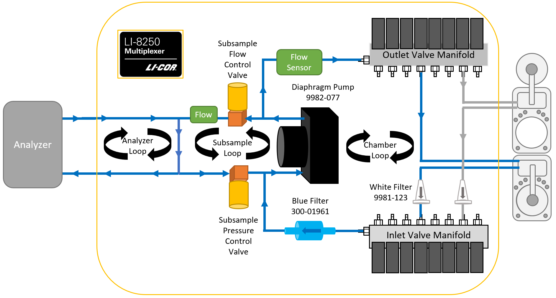
During the System Leak Test, the LI-8250 Multiplexer pump draws a vacuum on each port. Pressure is monitored to determine the total leak rate for that port. Before moving to the next port, the system is purged to prepare for the next port to be tested. Leak rates over 1 cm3 s-1 indicate a leak should be fixed.
Note: During the leak test, one or more ports must be left open to allow the system to purge itself. The port that is left open will can be checked for leaks after testing the others.
To perform the System Leak Test:
-
In the LI-8250 interface, click Tools > Leak Test.
The System Leak Test is selected by default.
-

- Disconnect the tubing from each gas analyzer and connect the disconnected ends together but leave the tubing connected to the multiplexer.
For the LI-78xx Trace Gas Analyzers, use a Swagelok union (part number 300-15249) to connect the tube ends together. For the LI-870, simply connect the fittings.
- Disconnect the tubing from each chamber and connect the disconnected ends together for each port to test but leave the tubing connected to the multiplexer.
Note: At least one port must be left open to allow the system to purge itself.


- If your system includes 8250-01 Extension Manifolds, for each extension manifold, disconnect the tubing from each chamber and connect the ends of the tubing together for each port to test but leave the tubing connected to the extension manifold.
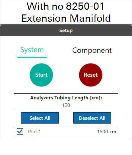
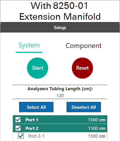
- In the interface, select the ports to test.
- Verify the tubing lengths for the analyzer tubing and the chamber tubing are representative of your system.
- These lengths are set in the Configuration page under the gas analyzer blocks and chamber blocks.
-
Select the ports to test (do not test the purge port that was left open).
-
Click Start.
This interface will issue prompts (two if you do not have an 8250-01 Extension Manifold, three if you do) asking you to verify that you have configured the system correctly. To begin the test click Start Test.
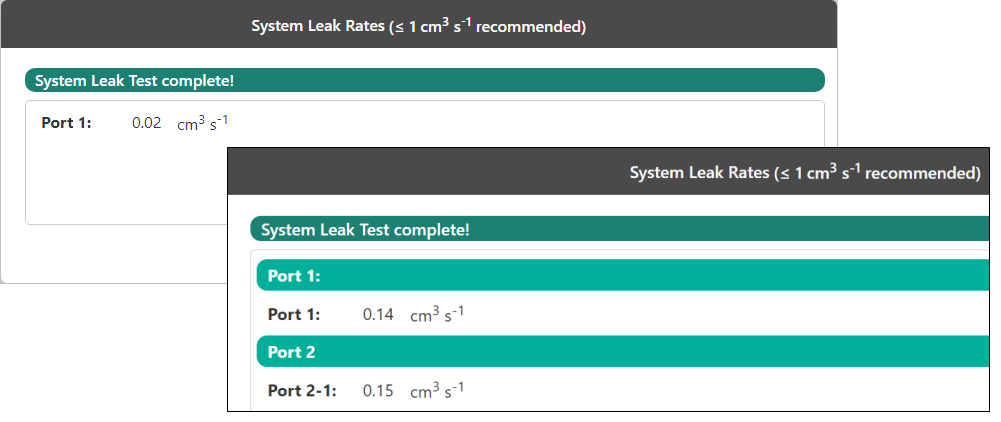
The multiplexer will then perform the System Leak Test. After the leak test, the system will provide a report on the system leak rate. If the report has no warnings, no issues were detected. You can test any ports that were not tested before, such as the purge port.
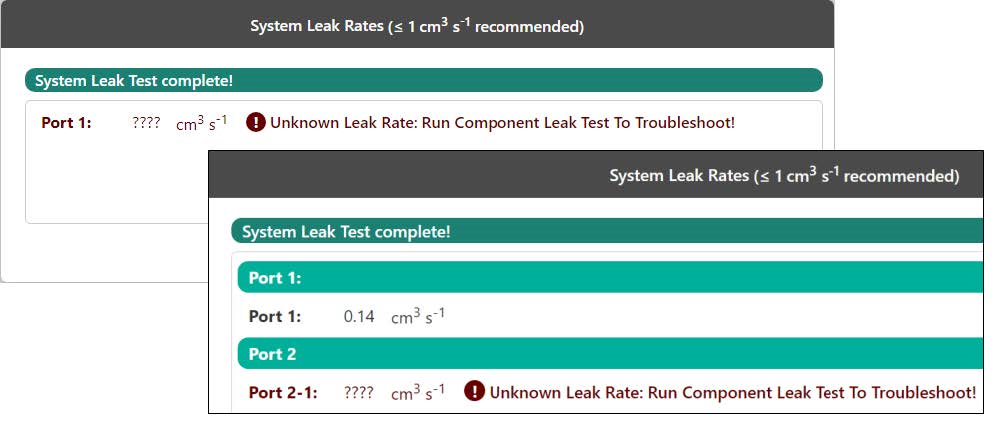
Any port that exceeds the 1 cm3 s-1 threshold for a leak will provide you with a high leak rate warning and advise you to run the Component Leak Test to troubleshoot where the leak may be occurring, see Figure 8‑3.
Component leak test
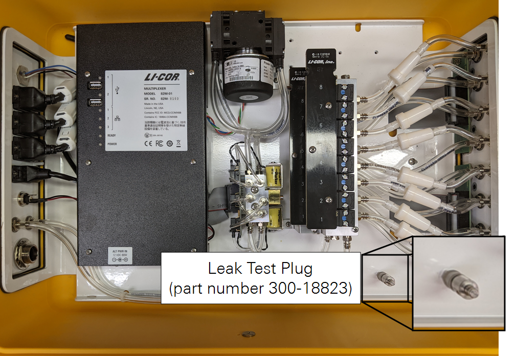
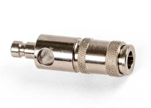
If the System Leak Test indicates that one of the ports has a leak, you can use the Component Leak Test to identify the leaking tube on that port. A quick-connect plug (part number 300-18823) is included with the LI-8250 for this test (see Figure 8‑4). The LI-8250 software interface will guide you through when to use the plug.
The Component Leak Test requires you to seal the analyzer tubing and the tubing of each tested port to form a closed loop. At least one port must be left open.
This test will check the following components for leaks on the LI-8250:
- Tubing to gas analyzers (not including the gas analyzers)
- LI-8250 tubing (subsample loop)
- Tubing between valve manifolds and ports (both In and Out are tested)
- Tubing between multiplexer and chamber (both In and Out are tested)
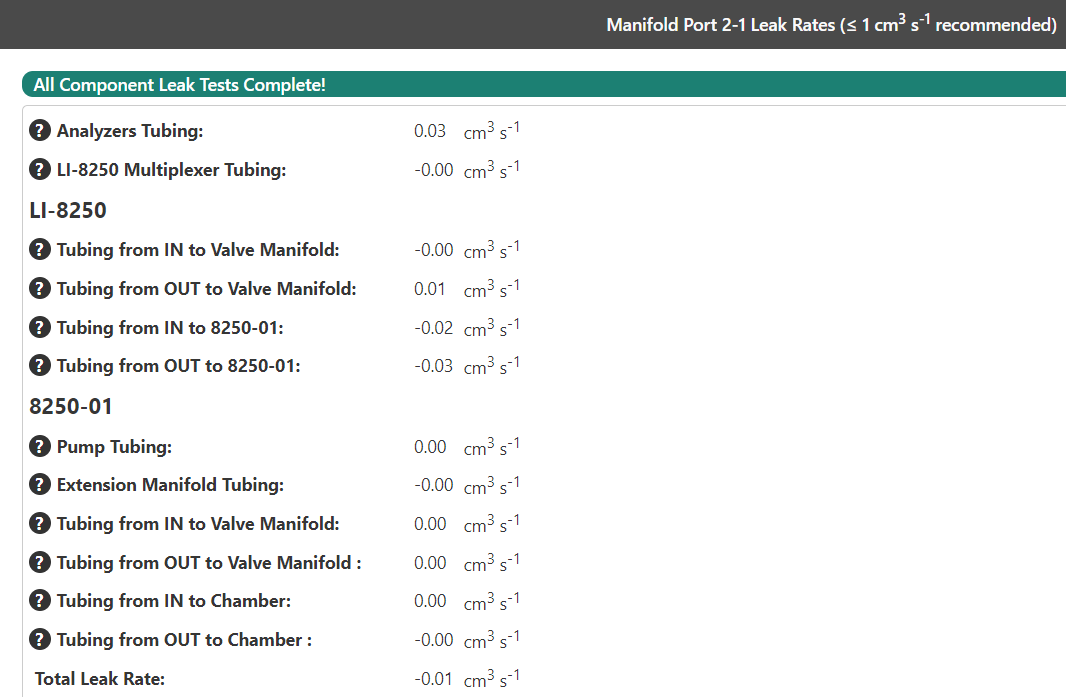
If the system is equipped with an 8250-01 Extension Manifold, the test will check the following components on the manifold:
- Pump tubing
- Extension manifold tubing
- Tubing between valve manifolds and ports (both In and Out are tested)
- Tubing between extension manifold port and chamber (both In and Out are tested)
Each subsequent step of the test relies on the previous steps to estimate the leak of that component. If one component exceeds the 1 cm3 s-1 threshold, you will receive a warning message under Component Leak Rates. The test will stop and indicate the component with the high leak rate that needs to be repaired. Repair the component with the high leak rate to continue the test.
To perform the Component Leak Test:
- In the LI-8250 interface, expand the Tools menu and select Leak Test.
- Disconnect the tubing from each gas analyzer and connect the disconnected ends together.
- Leave the tubing connected to the multiplexer.
- Disconnect the tubing from each chamber and connect the disconnected ends together for each port to test.
- Leave the tubing connected to the multiplexer.
Note: At least one port must be left open to allow the system to purge itself.
-
Click Component and select the port or port combination (if using the 8250-01) to test.

-
Verify the tubing lengths for the analyzer tubing, Extension Manifold tubing (if using the 8250-01), and the chamber tubing are representative of your system.
These lengths are set in the Configuration page under the gas analyzer blocks and chamber blocks.
-
Click Start.
This interface will issue a prompt asking you to verify that you have configured the system correctly. To begin the test click Start Test.
-
Proceed through the prompts.
After the gas analyzer tubing is tested, the interface will ask you to connect the leak test plug to the chamber IN connection and test that component, followed by the chamber OUT connection, and finally, between the ends of the chamber tubing.
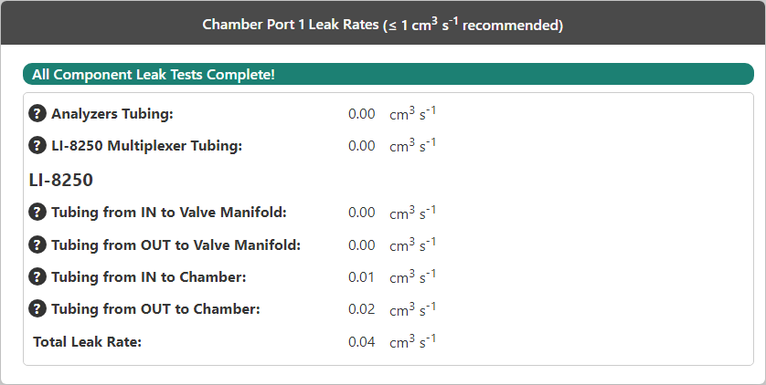
Each individual component is tested, and if a leak is detected, it will be indicated in the results. If the Total Leak Rate exceeds 1 cm3 s-1, you will see a warning to address the areas with a high leak rate. It is possible to have no individual components exceed the threshold but to have a cumulative total > 1 cm3 s-1, in which case, you should fix some leaks.
Note: The total leak rate measured by the Component leak test may differ from the System leak test leak rate because the System leak test is more accurate.
Leak testing systems configured for flask measurements
If your LI-8250 has been customized for flask measurements, you must plug two ports that were opened for the customization to do the System Leak Test. If you do not want to modify the multiplexer for this test, you can skip the System Leak Test and just do the Component Leak Test instead.
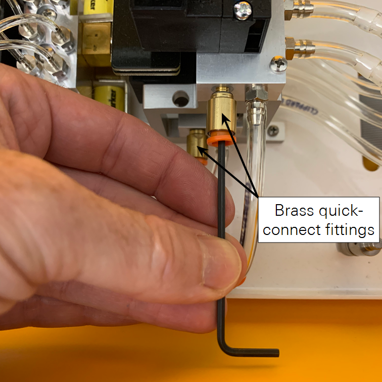
To customize for the System Leak Test, insert a 5 cm piece of tubing into each of the two fittings indicated in Figure 8‑7 and seal the openings with a hemostat. Alternatively, you can reinstall the two brass plugs that were removed before installing the quick-connect fittings. After completing the leak test, restore any alterations to the tubing.