The LI-840A can be connected to a constant source of AC power using a transformer that provides 12-30VDC (14 watt maximum) to the LI-840A. If the LI-840A is powered with a voltage below 10.5 volts, the analyzer will not power up, and the Low Battery LED on the top panel will illuminate. The LI-840A will continue to operate with a low battery; there will, however, be a corresponding reduction in performance.
Alarms
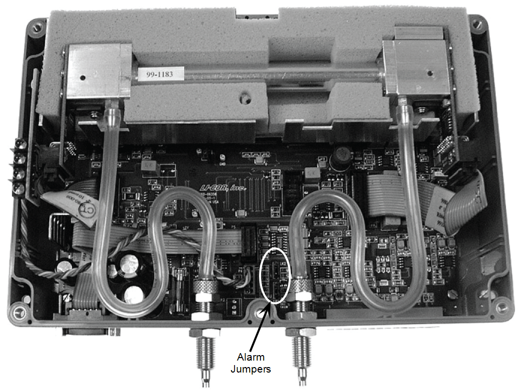
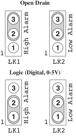
The LI-840A is equipped with high and low alarms, which can be configured as open collector or 0-5V output (TTL levels) using jumpers on the main PC board (). The default configuration is 0-5V output. Figure 2‑2 shows the position of the jumpers for each of the two alarm conditions.
Note: The alarms can be used for either CO2 or H2O concentrations; only one can be chosen at a time, however.
In addition, a "dead band" value can be set in software for both high and low alarms. To understand how the alarms and dead band values work, look at the diagram below.
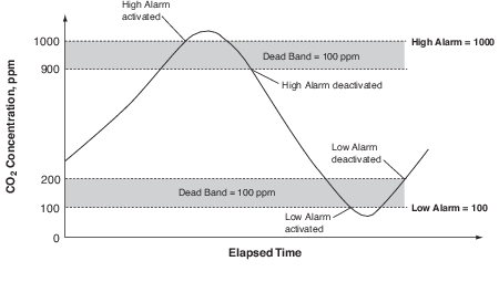
In this chart, the low and high alarm values are set to 100 ppm and 1000 ppm, respectively. The dead band value in both alarms is set to 100 ppm. When the CO2 concentration reaches 1000 ppm, the high alarm is activated, and remains active until the concentration drops below 900 ppm. When the CO2 concentration falls below 100 ppm, the low alarm is activated, and remains active until the concentration rises above 200 ppm. Your choice for the dead band value(s) depends on your application and the fluctuation in CO2 concentrations over time.
Note: Increasing the signal average value in software (see Settings Window; Options; Filter in Section 3) can help reduce fluctuations in readings.
Alarm LEDs can be viewed on the top panel of the LI-840A. Terminals 3 and 5 on the terminal strip are also connected to the High and Low alarms, respectively. This is useful for connecting an audible alarm, for example, or a relay switch to operate another device that will raise or lower the CO2 concentration to the desired level. The schematic diagram below shows how the high alarm could be connected to a relay switch that triggers an exhaust fan in a greenhouse environment. These relays could also be used to trigger devices such as automatic dialers, alarms, pumps, and valves in industrial and other environments.

A list of suppliers of electronic relay switches can be found in Appendix D.
NOTE: Consult your local electrical codes before wiring, and/or have a professional electrician wire your application.