System Overview
The LI-840A CO2/H2O Gas Analyzer is an absolute, non-dispersive, infrared (NDIR) gas analyzer based upon a single path, dual wavelength, infrared detection system. The CO2 and H2O measurements are a function of the absorption of IR energy as it travels through the optical path. Concentration measurements are based on the difference ratio in the IR absorption between a reference and sample signal. Reference and sample channels measure infrared gas absorption in a single path through the use of narrow band optical filters with appropriately selected bands. The CO2 sample channel uses an optical filter centered at 4.26 micrometers, corresponding to an absorption band for CO2. The reference channel for CO2 has an optical filter centered at 3.95 micrometers, which has no absorption due to CO2. The H2O sample channel uses an optical filter centered at 2.595 micrometers, corresponding to an absorption band of H2O. The reference channel for H2O has an optical filter centered at 2.35 micrometers, which is a non-absorbing region for H2O.
The instrument uses digital signal processing techniques to determine the temperature and pressure corrected CO2 concentration based on the optical bench signals using a ratiometric computation. The data are passed through a double rectangular hyperbola (CO2) or 3rd order polynomial (H2O) that performs linearization of the detector signal to a mole fraction in air given in µmol CO2 per mole of air (ppm), and mmol H2O per mole of air (mmol/mol).
Data output is provided in a digital format through an RS-232 interface that supports connection to an external computer. The instrument comes with Windows®-compatible software for instrument configuration, control, data collection and display. Analog signals are available through a terminal block for collection by a data logger or similar means.
Optical Bench System
The LI-840A CO2/H2O Gas Analyzer optical path is a thermostatically controlled IR detection system. The optical bench operation is based upon a broad band IR source and a pyroelectric detector. The source is mounted in a parabolic reflector to collimate the light and increase energy throughput down the optical path to the detector. The reflector and optical path are gold plated to further increase energy transmission. The detectors are pyroelectric devices that operate based on thermal energy received. The narrow band optical filters allow only the wavebands of interest to illuminate the detector, allowing for the determination of CO2 and H2O concentrations in the presence of other infrared absorbing gases.
The detectors respond to thermal energy, so it is necessary to precisely regulate the detectors’ temperature. This allows for differentiation of thermal gradient noise from the received signals from the optical path. The detection system is shown in Figure 4‑1.
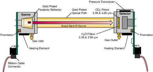
The optical bench has a thermostat that maintains a constant operating temperature of 50 °C. A feedback loop is used to regulate the optical bench temperature. As shown in Figure 4-1, two thermistors, located in the source and detector housings, measure the present temperature. The thermistors are monitored as part of the control loop to determine corrections necessary in the thermal balance. Two heating elements are the sources of thermal energy into the source and detector housing. The optical path is in mechanical contact with the source and detector housing and thereby achieves thermal equilibrium.
The bench requires approximately 10 minutes to achieve the specified thermal temperature. A longer period of approximately 20 minutes is required to bring the performance of the detection system to within 1 to 2% of reading. As shown in Figure 4‑1, the detector housing has a pressure transducer integrated into the housing design. Part of the CO2 concentration calculation depends on the pressure observed in the optical path, measured with an in-line pressure transducer. Many parameters can affect the pressure and thus the concentration reading. The processing center in the analyzer reads the pressure reading as part of its data collection task and uses this information in the concentration calculation. The gas flow enters the source housing, passes down the optical path and exits at the detector housing. The maximum flow rate for the analyzer is approximately 1 liter/min.
Another key parameter in the concentration calculation is the gas temperature in the optical path. It is assumed in the analyzer operation that the gas temperature will equilibrate to the optical bench temperature (50 °C) by the time it enters the optical path. Since the instrument performs temperature and pressure corrections as part of the concentration calculation, this assumption is very important. To cause the sample air to equilibrate to the optical bench temperature, an airflow pattern is created with sufficient eddy currents to cause thermal equilibration.
The optical bench is mounted in a foam enclosure to accomplish two purposes. The first is to assist in maintaining the controlled thermal environment required for the optical bench as described above. The second function of the foam enclosure is to protect the optical bench from mechanical shock and vibration that might damage the mechanically sensitive components. The foam enclosure is supported by a optical bench “tray” which is in turn attached to the main circuit board (PCB). The optical bench is mechanically de-coupled from the case by creating the s-bend in the Bev-a-line tubing from the external fittings to the optical bench gas inlet and outlet connectors. The electronic interface to the source and detector is achieved through printed circuit boards mounted directly to the source and detector housings, respectively. The PCBs connect the main PCB to the source and detector PCBs via a ribbon cable. This achieves the mechanical isolation desired for the optical bench.
A 14 cm (5.5") optical bench provides a CO2 measurement range of 0 – 20,000 µmol/mol (ppm), and an H2O measurement range of 0 – 60 mmol/mol.