Maintenance
Cleaning the optical bench
The LI-870 optical bench can be removed and cleaned with just a few steps if necessary. Generally speaking, you shouldn't undertake this procedure unless you've ruled out other potential problems. While the process itself is not difficult, you will have to set the instrument zero and span after reassembling the optical bench.
An optical bench cleaning kit (part number 9980-066) is included with your LI-870 spares kit. You will also need a small Phillips screwdriver. Follow these steps to remove and clean your optical bench and replace the O-rings. Note that the images included in this section were taken from a prototype LI-870. The wiring and plumbing in your instrument may appear slightly different.
Warning: Be sure that you are properly grounded to avoid electrostatic discharge that can damage the electronics. Use an anti-static wrist strap, electrostatic discharge grounding mat, or occasionally touch bare metal that has a clear path to ground, such as an unpainted computer case.
- Unplug your instrument from the Smart Chamber or LI-8250. If you've been operating the instrument recently, you should allow the optical bench to cool down to room temperature.
- Open the analyzer and remove the plate covering the optical bench.
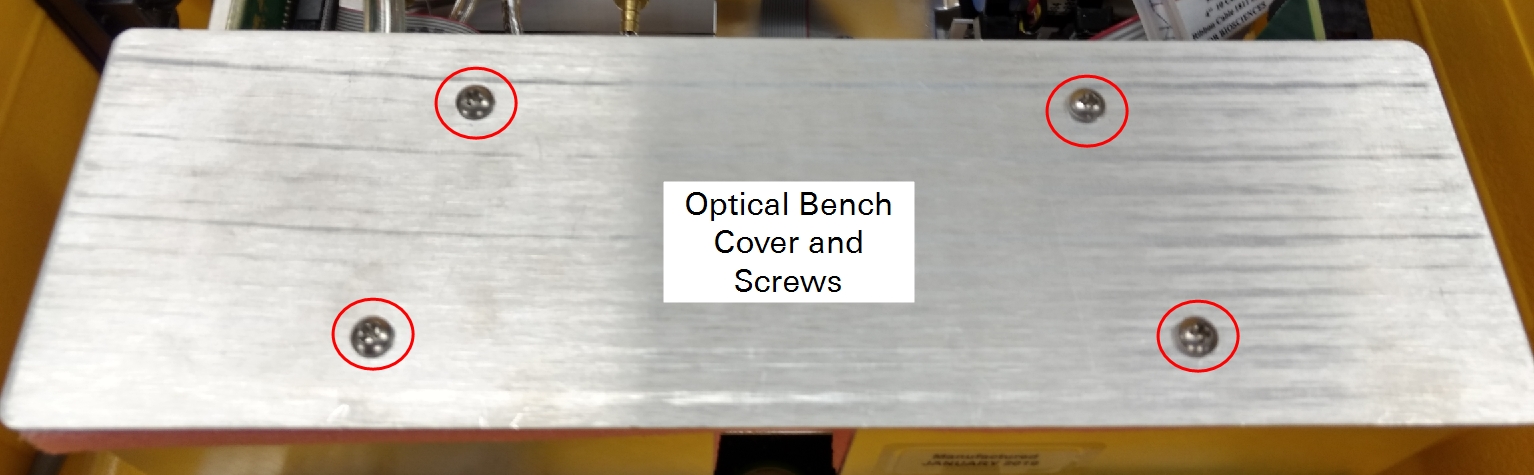
- The bench cover is held in place by four screws. Remove these screws, remove the plate and foam, and set aside. The insulated optical bench will now be visible.
- Gently lift the optical bench out of the insulating foam and remove the cable connectors from the source and detector circuit boards.
-
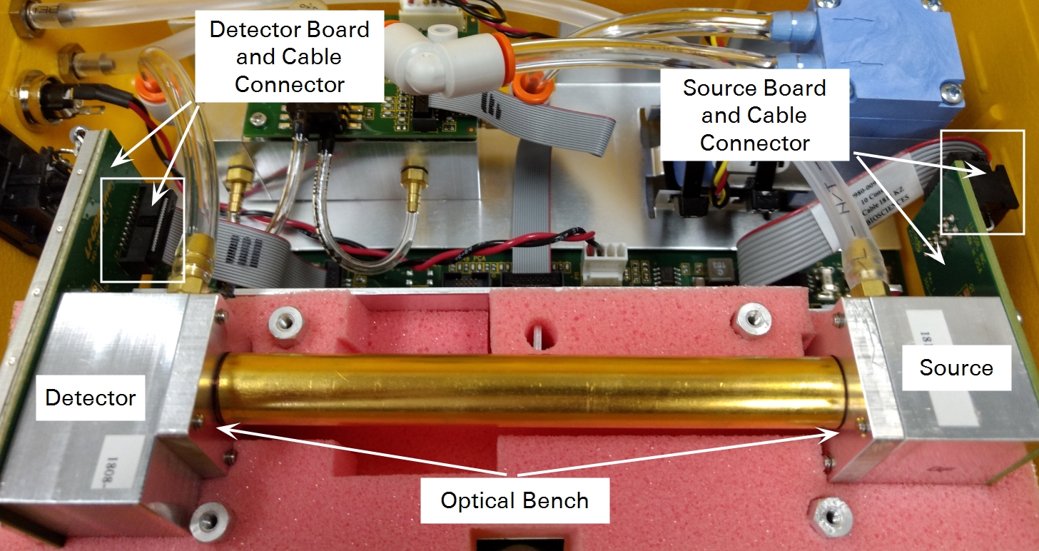
- Gently grasp the plugs and pull them free.
-
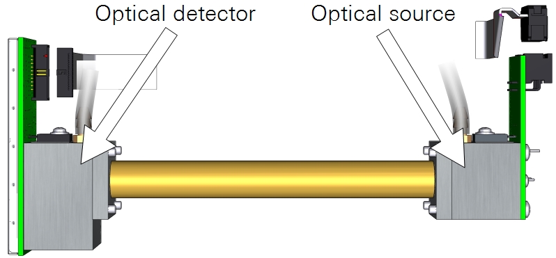
- Remove the screws that secure the source and detector (4 each), then separate the source and detector housings (with circuit boards attached) from the optical path.
-
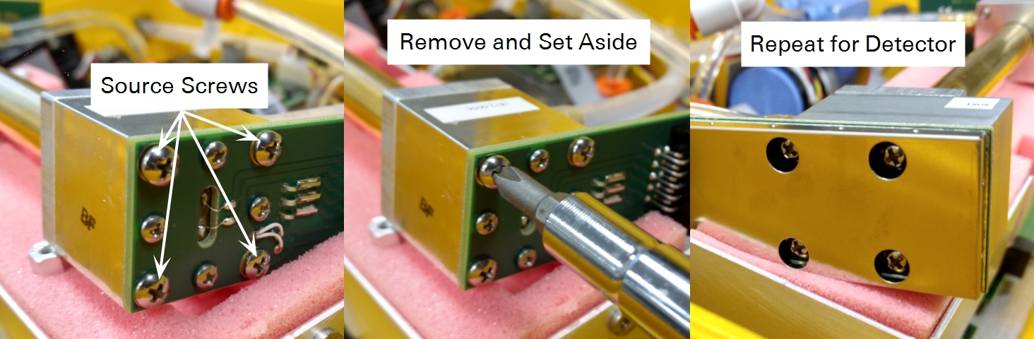
- Clean the optical bench, source, and detector.
- Retrieve an optical path swab from the accessories kit.
-
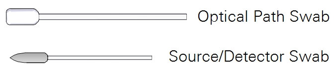
- Dip one end into a 50:50 ethanol:water mixture (mild dish washing soap and water will work too) and carefully swab both ends of the optical path. Then, dip a Source/Detector swab into the solution and then swab around the source and detector to remove any residue.
Warning: Do not use abrasive cleansers. Abrasive cleaners can irreparably damage the gold plating on the optical path, source, or detector.
- Inspect the hose barbs and tubing.
- If the tubes are dirty or damaged, cut a new length of tubing from the extra tubing included in your spares kit, and replace them. Carefully remove them from the hose barbs. If the tubes are in good condition and clean, you may be able to reuse them. If the hose barbs are dirty, remove them and clean them with rubbing alcohol or soapy water. Use caution and do not scratch the hose barbs because scratches may cause leaks.
- Inspect the O-Rings.
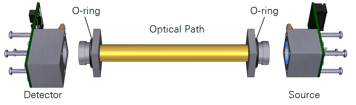
- Four O-rings are included in the Optical Bench Cleaning Kit (part number 9980-066), and additional O-rings can be purchased from LI-COR. Replace them if they are smashed flat or damaged in any way.
- Let the optical components dry and reassemble the optical bench.
- Attach the source and detector. The orientation of the optical path cylinder is unimportant — either end can be inserted into the source and detector housing. Tighten each of the screws snugly.
- Place the optical bench back into the foam, re-insert the cable connectors to the source and detector, and screw the cover plate back to complete the re-assembly.
- Perform a zero and span calibration (see User calibration for instructions).
Connecting to LI-870 for calibration
Though the primary interface for the LI-870 is through the Smart Chamber or LI-8250 software, you may also connect your LI-870 to the LI-COR LI-830/850 software to view data and for user calibration.
After downloading and installing the software from the LI-COR support site (licor.com/support), launch the software. It should display No Analyzer Connected.
Note: You must connect the power cable from a powered-on Smart Chamber or LI-8250 to power to analyzer when using the software.
Connect your analyzer to your computer using the USB-B to USB-A cable included with your purchase. You may see a notification that says Setting up device, or something similar. After the automatic device setup is complete, go back to the software, and click Connect. In the box that opens, expand the Connect to drop-down menu, and you will see your device.
Important: The LI-830/850 software will recognize your LI-870 as an LI-850. This is normal. Go ahead and click Update, and you will connect to your LI-870.
After connecting, the software presents you with live data and graphs.
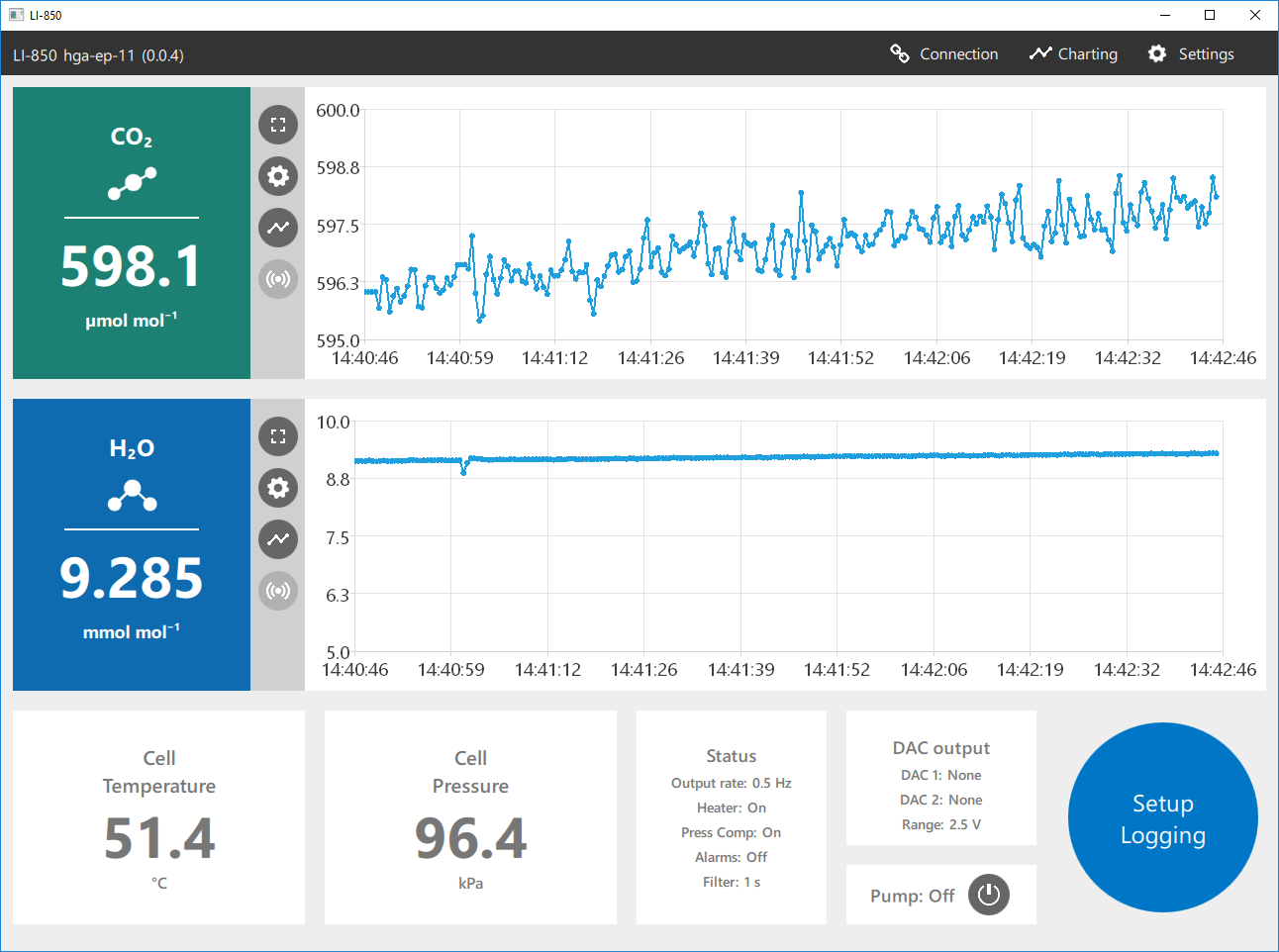
Here you can see important diagnostic information like Cell Temperature and Cell Pressure. You can also turn the pump on by clicking the power button next to Pump: in the bottom-right of the software.

The software offers a variety of other features you may choose to explore. A more thorough explanation of the software is available at the LI-COR support site. However, for LI-870 soil applications, you will likely only the use the software for instrument calibration.
User calibration
If the instrument is not measuring as expected, or if you have disassembled the optical bench for any reason, you should check the zero and span settings and set them if necessary. The zero and span are an offset and slope. The zero value ensures that the instrument shows zero when the gas has a zero concentration. A change in the zero will affect every measurement. The span setting ensures a correct measurement at a known non-zero concentration. A change in the span affects higher concentration measurements more than lower ones. The recommended order of operation for user calibration is
- Set the H2O zero.
- Set the CO2 zero.
- Set the H2O span.
- Set the CO2 span.
For user calibration, additional tubing (part number 222-01824) and quick connects (part numbers 300-07124 (male) and 300-07125 (female)) are included with your spares kit.
Setting the H2O zero and spans
The water vapor span can be set with a dew point generator such as the LI-610. The procedure is the same as setting the CO2 zero and spans, only this uses known concentrations of water vapor rather than CO2.
Caution: Setting the zero and span incorrectly for either CO2 or H2O will adversely impact the performance of your instrument. If you do not have the proper equipment to span the analyzer, it is best to leave it alone.
Setting the CO2 zero
Always perform the zero first. To set the zero, you'll need either a tank of dry air that is free of CO2 or a CO2 scrubbing chemical such as wet soda lime and a desiccant such as Drierite.
- Plumb the zero-gas tank or scrubber to the air inlet.
- Be sure to use an air filter to prevent contaminants from entering the optical path.
-
- If using tank air, the pressure of the tank is sufficient to flow the gas through the analyzer. Allow at least 0.75 liters per minute to flow through the cell (no more than 1.0 lpm).
- If using a scrubbing chemical, use a pump to draw air through the analyzer.
- Install a 10 to 20 cm length of tubing to the air outlet.
- This vent prevents ambient air from diffusing upstream into the optical cell.
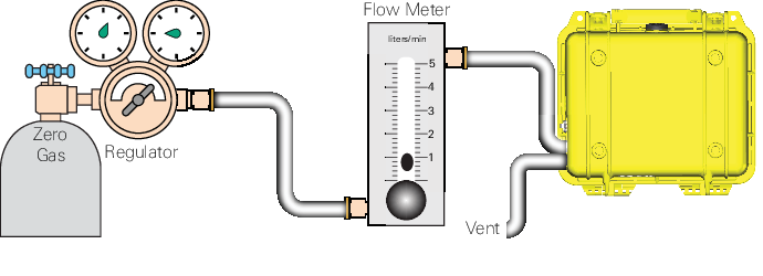
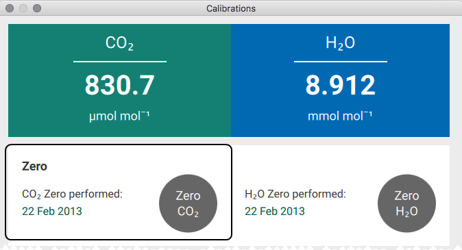
- When the CO2 concentration has stabilized, click the Zero CO2 button.
Setting the primary CO2 span
When choosing a span gas, we recommend a gas concentration that is close to - but still slightly above - the upper limit of what you expect to measure. For example, if you are measuring near-ambient levels, choose a span gas that is near 400 ppm CO2 (as opposed to 18,000 ppm). Similarly, if you are measuring concentrations near 15,000 ppm CO2, a span gas with 100 ppm would not be ideal.
- After zeroing, flow a gas with a known CO2 concentration through the analyzer at a rate of 0.5 liters per minute.
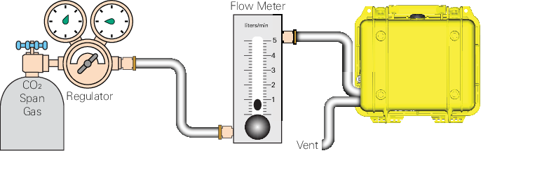
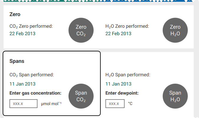
- Enter the CO2 concentration of the span gas into the software.
- When the CO2 reading has stabilized, click Span CO2.
Setting the secondary CO2 span
You can set a second span (using a gas that has a CO2 concentration that is higher or lower than the primary span gas) to improve the precision of the analyzer. The process is exactly the same as setting the primary span, only you'll enter a different concentration and click Span2 CO2.
Recovering from a bad zero or span
If your attempt to zero or span does not go as planned, you can restore the factory default zero and span settings. The information you need is provided on the calibration sheet (included with the instrument or available for download from licor.com/support/home.html). Under Settings > Calibrations > Advanced, enter the factory zero and span values for your instrument.