Authors: LI-COR, Inc.
Correspondence: envsupport@licor.com
Published: 2021
Instruments: Smart Chamber, LI-7810, LI-7820
Keywords: soil survey chamber, two gas analyzers
Abstract
Many users wish to connect multiple LI-COR Trace Gas Analyzers to the Smart Chamber soil survey system to allow the simultaneous flux quantification of multiple gas species. The Smart Chamber allows for data integration and automatic flux calculation from one TGA, and we can import and calculate new fluxes from additional analyzers using SoilFluxPro™ Software (SFP) version 5 from LI-COR.
Here we refer to the most commonly used combination using the LI-7810 for CH4 and CO2 measurements and the LI-7820 for N2O measurements, but the same general procedure can be used to connect any two LI-COR TGAs.
1 | Parts needed
Some hardware is needed, in addition to the Smart Chamber and gas analyzers.
| Description | Quantity | Part Number |
|---|---|---|
| 2 m Cable Assembly | 2 | 9982-011 |
| Two-analyzer T-split tubing | 1 | 9982-073 |
Data processing will be completed in SoilFluxPro™ Software. Version 5 is available for download from licor.com/support/SoilFluxPro/home.html
2 | Air connections
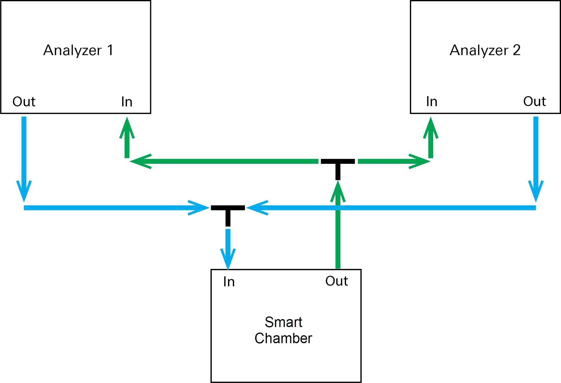
The Smart Chamber and analyzers will be connected to create a continuous loop through all three system components (Figure 1). This configuration requires a two analyzer T-split and two 2 m cable assemblies. You can recreate this arrangement using custom tubing lengths if you prefer. The pre-made assemblies are available for convenience and performance.
Connect the T-split long leg (15 cm) to the respective IN or OUT port on the Smart Chamber. Attach the 2 m assemblies to the T-split, and one to each of the TGAs. Take care to ensure the correct direction of flow. Air should flow out the analyzers in to the chamber, and out from the chamber in to the analyzers. The ends with black plastic shrink wrap go to the Smart Chamber outlet and TGA inlet.
3 | Software setup
- Power on the Smart Chamber and TGAs.
- The following steps can be performed whilst the analyzers are warming up.
- Connect the LI-7820 N2O analyzer to the Smart Chamber using the supplied Ethernet cable.
- Check that the Smart Chamber has obtained GPS lock (Figure 3).
- This will ensure that the Smart Chamber clock is synchronized to the correct time. To obtain GPS coordinates, you may need to do this outside if working in a tall building.
-
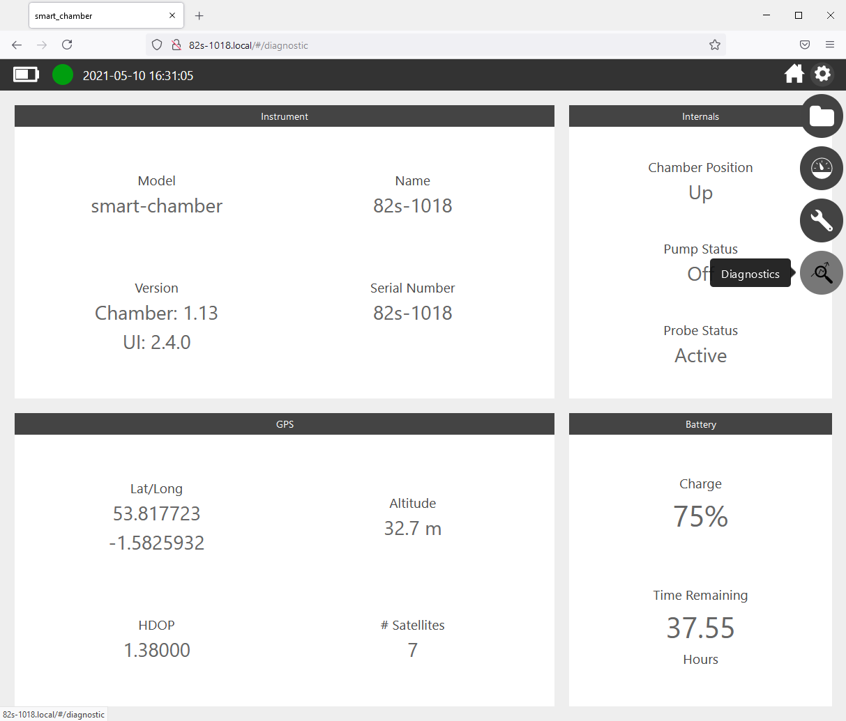
Figure 3. Smart Chamber diagnostics page showing that it is connected to multiple satellites and confirming that the chamber has achieved GPS lock. - From your PC or mobile device, connect to the LI-7820 embedded web server and navigate to Settings > Time.
- Ensure the boxes for Auto Sync and NTP are checked as in Figure 4. In the server address box enter the serial number of your Smart Chamber (e.g. 82s-XXXX) followed by .local. Click update and the time shown will adjust to match the Smart Chamber GPS clock.
-
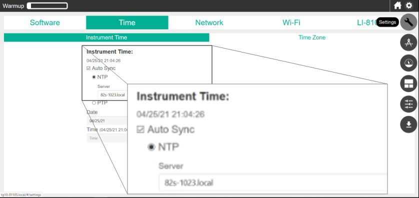
Figure 4. TGA time settings to ensure that data is well aligned. - Note: By pre-synchronizing the LI-7820 clock before measurements you eliminate the need to manually align the data and improve the ease of processing.
- Disconnect the Ethernet cable from the LI-7820 assembly from the Smart Chamber and TGA.
- It will remain disconnected in the assembly during measurement.
- Connect the LI-7810 to the Smart Chamber via Ethernet.
- Optional: If you wish to re-analyze raw data from the LI-7810 you may wish to repeat step 4 to synchronize the LI-7810 clock. This is not required if you will only work with the Smart Chamber data file, which will automatically use the Smart Chamber clock for its timestamps.
- From the Settings page, configure the Smart Chamber to make measurements with the LI-7810 as normal, entering output file, soil type, observation length, replicates etc.
- Take care that your observation length is suitable to give a reasonable measurement of flux for all gas species.
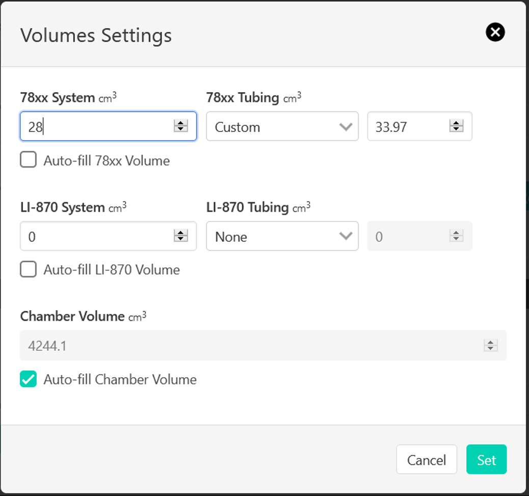
- Open the Set Volumes screen and enter the tubing and analyzer volume for a single analyzer as shown in Figure 5.
- A custom tubing is selected as the T-split will add 15 cm for each analyzer. This gives a total tubing volume for the 2 m assembly plus T-split of 33.97 cm3. This is a slight underestimation of total system volume, but it has a small effect as it is a small proportion of the total volume. This underestimation will be accounted for later when we import the LI-7820 data.
- Make your measurements.
- When completed, download your collected data from the Smart Chamber (which contains fluxes calculated from CO2 and CH4 measurements from the LI-7810) and concentration data from the LI-7820.
4 | Load Smart Chamber data file into SFP
- Load the .json data file from the Smart Chamber into SoilFluxPro.
- From the file management bar select the Import function
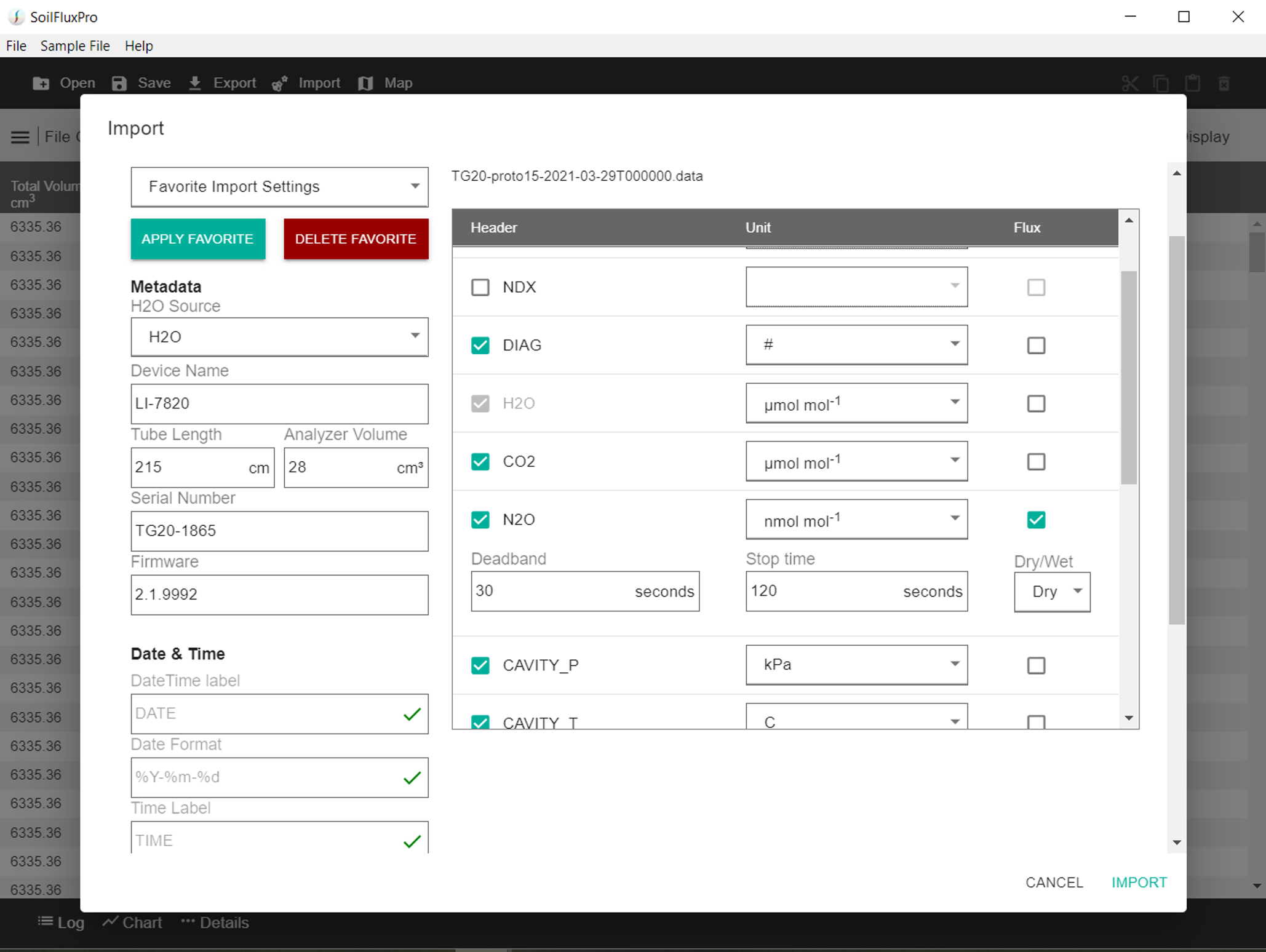
- In the Import screen set up your N2O data import as shown in Figure 6.
- Metadata should automatically populated from your LI-7820 data file, but you will need to enter an appropriate tube length – 215 cm if following this guide.
- Ensure that N2O concentration is selected with appropriate units (nmol mol-1). Select the check box for N2O flux and enter appropriate Deadband and Stop time settings.
- Once all required variables are set, tap IMPORT at the bottom of the screen.
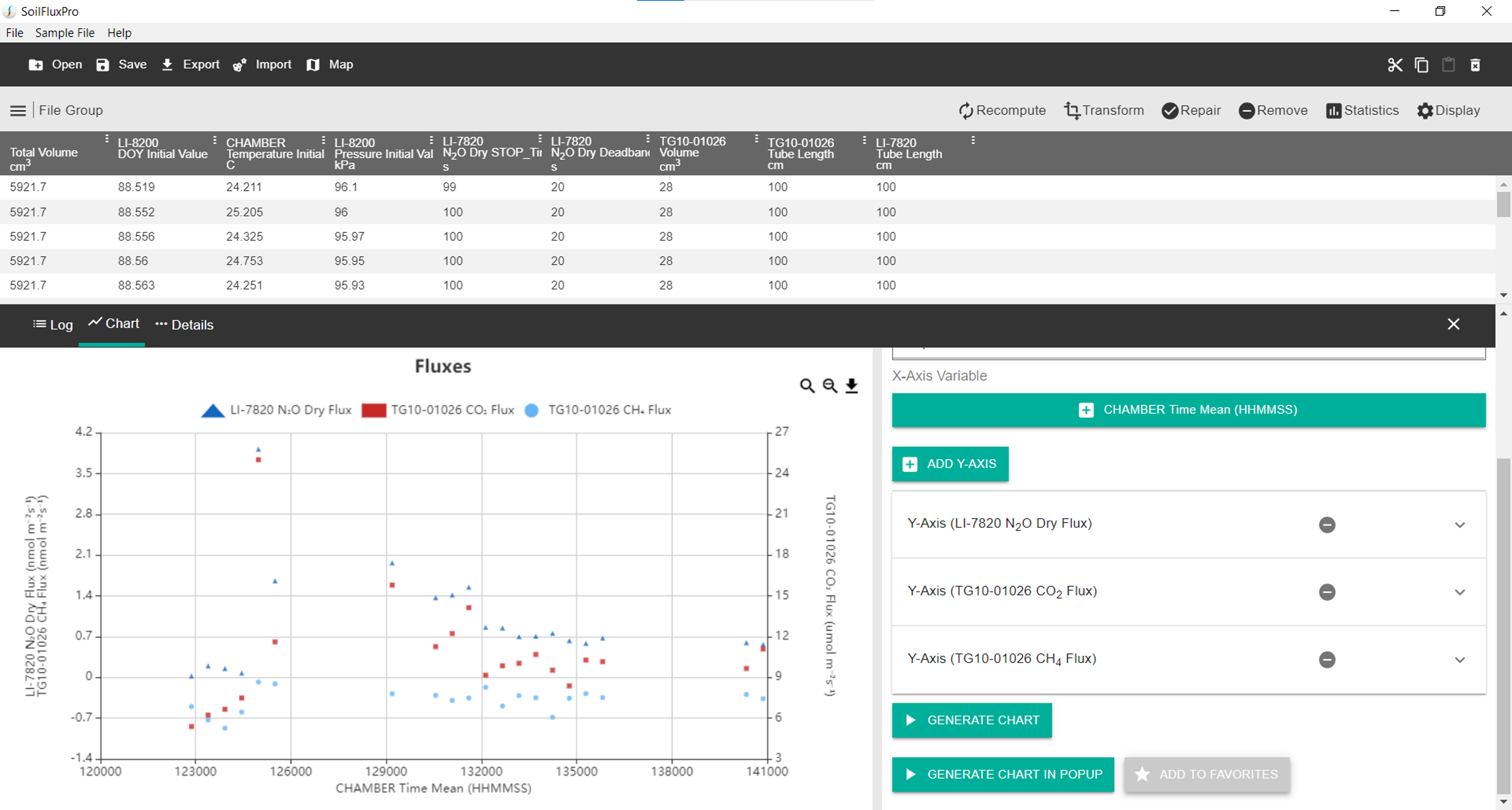
Imported data will be added in a new group according to the Device Name that you set above (default LI-7820). Flux(es), metadata, and so on, can be displayed, charted, or exported in SFP using the normal procedure from their appropriate groups.
5 | Useful Links
- Smart Chamber documents and software: licor.com/support/Smart-Chamber/home.html
- Trace Gas Analyzer documents and software: licor.com/support/Trace-Gas-Analyzers/home.html
- SoilFluxPro Software v5: licor.com/support/SoilFluxPro/home.html