Measuring pCO2 and Dissolved Inorganic Carbonates in Water
Printable PDF: Measuring pCO2 and Dissolved Inorganic Carbonates in Water
A description of pCO2 and DIC systems.
Oceans have a significant role in the global carbon budget, but spatial and temporal variation in ocean-atmosphere CO2 exchange is not well understood at the global level. As a result, many scientists are undertaking efforts to evaluate and characterize oceanic CO2 fluxes. This document provides brief descriptions of underway pCO2 systems, autonomous buoy pCO2 systems, and DIC systems.
When calculating CO2 flux for a body of water, measurement of either the partial pressure (pCO2) or total dissolved inorganic carbon (DIC) in the surface water is necessary. These measurements involve 1) collecting a water sample and ancillary data, 2) equilibrating the partial pressures of CO2 for a water sample and carrier gas in an enclosure for measurement of pCO2; or stripping inorganic carbonates from the water sample with an acid for measurement of total DIC, 3) measuring the CO2 mole fraction in the gas sample, and 4) calculating partial pressure of CO2 or total dissolved inorganic carbon for the water sample. For studies of the global carbon cycle, aqueous CO2 measuring systems are often deployed on Volunteer Observing Ships (VOS), research vessels, autonomous monitoring buoys, or in laboratories.
Underway pCO2 systems
Underway pCO2 systems, which are often operated either autonomously or semi-autonomously, are deployed in VOS or research vessels. The configuration of an underway system may depend on research objectives and constraints presented by the vessel in which it will be deployed. For example, a system that is to be deployed on a VOS may need to be designed for small size, low power requirements, and fully autonomous operation.
System components and operation Underway pCO2 systems are comprised of sampling hardware, an analysis system, and a data logging and transmission system.
The sampling hardware consists of:
- A seawater supply line, which may be mounted at the front of the vessel or on a sampling platform such as the Lamont Pumping SeaSoar (Hales and Takahashi, 2002)
- A drain for disposing of sampled sea water
- A deck mounted atmospheric air supply line
- Ancillary data collection instrumentation to measure temperature and salinity of seawater at intake, GPS position, time, depth of intake, and barometric pressure
- Optional data collection instrumentation to conduct fluorometry, measure relative humidity, and dissolved oxygen content
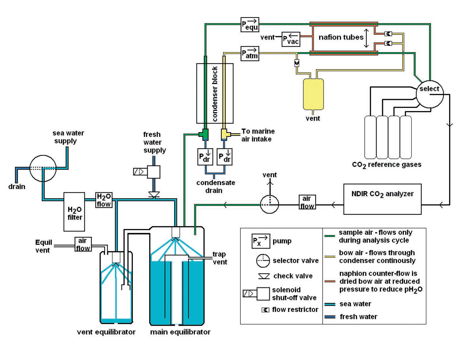
The analysis system (Figure 2) includes:
- An equilibrator
- Ancillary data collection instrumentation to measure temperature and pressure in the equilibrator
- A condenser and/or naphion tubes to remove moisture from sample gases
- An Infrared CO2 Gas Analyzer (IRGA)
- 2 or more gas standards for calibration
- Plumbing and circuitry
The data collection system includes:
- A data logger or data logging computer software and a computer
- Optional hardware to transfer data to shore using wireless communications technology
Equilibrators
The equilibrator serves to ensure that the partial pressures of CO2 in the water sample and head space gases are in equilibrium. Numerous equilibration systems have been used effectively, including shower head (Wanninkhof and Thoning, 1993), percolating packed bed (Cooper et al., 1998), bead (Frankignoulle et al., 2001), laminar flow (Poisson et al., 1993) and membrane contactor (Hales et al., 1994) equilibrators. There is considerable variation in overall volume and response time between equilibrators.
Shower head equilibrators are among the most commonly used, with volumes ranging from 2 to 60 L (Wanninkhof, 2004). One advantage of large volume shower head equilibrators is thermal inertia.
Since the volume of water in the equilibrator is large and flow rates are often high, the water temperature changes little between sampling and equilibration (Sutherland et al. 2003).
In addition, errors resulting from the accumulation and subsequent decomposition of organic matter are lower in large volume equilibrators. The disadvantages are that they occupy a lot of space, tend to have slower response times, and rely upon high flow rate pumps, which have high power requirements. For VOS, small volume equilibrators (~1.5 L) with low flow rates (1.5 L/min) are recommended. This necessitates high precision measurements of temperature of the equilibrator and intake water, and pressure in the equilibrator head space and atmosphere (Underway pCO2 Systems Workshop, 2002). Some researchers recommend multistage equilibrators in order to achieve full equilibration more reliably (Neill et al., 2007). Others describe the use of contactor membrane based equilibrators (Hales et. al., 2004), which have the advantages of small size and fast response.
An additional consideration is whether or not to vent the equilibrator to the atmosphere. Venting ensures that pressure in the equilibration chamber is equal to atmospheric pressure, reducing the need for mathematical pressure corrections. A drawback of venting is that atmospheric gases may be drawn into the system. Some investigators have placed a deflated balloon on the vent, ensuring balanced pressure while changing the system volume negligibly and preventing contamination by ambient air.
Measurement configuration
Because equilibrated gas samples are often saturated with water vapor, it is often desirable to reduce the moisture content of the gas sample prior to analysis. It is not necessary to entirely dry a gas sample because many LI-COR IRGAs can be configured to mathematically correct for band broadening and absorption by H2O; however, there is a risk that condensation will form in the tubing or IRGA chamber when humid samples are analyzed. This will compromise results and may damage the analyzer.
The two commonly used methods for gas sampling with an IRGA are continuous (Goyet and Peltzer, 1994) and stopped (Takahashi et al., 2002) flow. When a system is configured for continuous flow, sample gases are passed through the IRGA at a constant rate, either in a closed or open loop.
With the stopped flow method, flow of the gas sample through the IRGA chamber is stopped momentarily during measurement. This may be useful when there is a need to limit the amount of standard gases used during calibration or when a limited volume of gas is available from the equilibrator. Both stopped flow and continuous flow can be used to make accurate measurements.
Earlier model IRGAs, such as the LI-COR LI-6251, do not calculate CO2 concentration and simply output millivolt values. Scientists who used these models were accustomed to calculating CO2 concentrations and corrections to account for IRGA optical cell temperature and pressure. Later model IRGAs are equipped with internal algorithms to calculate CO2 and H2O (when applicable) concentration with great precision, including the effects of temperature, pressure, and water vapor (dilution and band broadening). While the temperature and pressure measurements in the IRGA optical cell provide an accurate CO2 measurement, changes in temperature and pressure that occur between the water intake and equilibrator will have to be accounted for as well. This is discussed below.
Sampling protocol
Sampling protocols for underway pCO2 systems vary widely. In general, a sampling protocol should be devised to accommodate the research objectives, the constraints presented by the vessel on which the system is deployed, and the parameters of the sampling system. A typical run sequence will include measurement of zero and span gases, ambient air samples, and equilibrator air samples.
Additional considerations
The list below includes descriptions of some challenges that are encountered by scientists who operate pCO2 systems. The list is derived from the proceedings of the Ocean Surface pCO2, Data Integration and Database Development (2004) workshop. It is not a comprehensive summary, but rather a description of some common challenges encountered when operating an underway pCO2 system.
- Any difference in temperature between water intake and equilibrator will have to be accounted for with a temperature correction. This occurs most noticeably with small volume equilibrators and low flow rate pumps. While changes in temperature can be accounted for mathematically, the application of thermal insulation to water supply lines will help reduce temperature changes.
- Pressure changes in the equilibrator resulting from changing water levels or unstable flow rates result in noise. Solutions include precise measurement of equilibrator pressure so mathematical corrections can be applied, and optimization of pump design and plumbing configuration to minimize fluctuations.
- The accumulation and decomposition of organic matter in an equilibrator or any component of the system will result in a positive bias. Recommended solutions are to use an equilibrator that does not require a filter, clean the equilibrator unit and filters often, or use high flow equilibrators. Neill et al. (2007) describe the use of fresh water back flow to clean filters.
- Circulating equilibrators tend to give a center oriented bias for samples that are at either a high or low extreme. Solutions are to minimize the need for re-supply air, increase equilibrator efficiency, pre-equilibrate resupply air, or use a closed loop configuration
Autonomous buoyed pCO2 systems
The operation principals of buoy mounted pCO2 monitoring systems are similar to underway systems, but generally, buoy systems must be smaller, use less power, and operate fully autonomously.
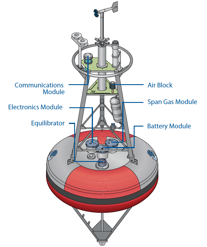
Extensive research, conducted by the Monterey Bay Aquarium Research Institute (MBARI) and the National Oceanic and Atmospheric Administration (NOAA), has resulted in the commercialization of a fully autonomous pCO2 system, which is made available through the Battelle group (Figure 3). This buoy-deployable system uses a LI-COR CO2 analyzer for gas analysis. To learn more about this system contact the Battelle group at www.battelle.org.
Dissolved Inorganic Carbon
Another measurement that can be used in calculations of ocean-atmosphere CO2 flux is total dissolved inorganic carbon (DIC). DIC refers to dissolved inorganic carbonates in an aqueous sample, including CO2, H2CO3, HCO3-, and CO32- (note that H2CO3, HCO-, and CO2 all result from CO2 + H2O ↔ H2CO3 ↔ H+ + HCO3 ↔ 2H+ + CO32-). DIC requires measuring the total CO2 in a sample, as opposed to the partial pressure measurement required for pCO2.
Battelle’s autonomous pCO2 monitoring system is designed to measure the partial pressure of CO2 in air and water in remote ocean environments. It features a measurement range of 100 to 600 ppm or greater, and precision of about 1 ppm. Built-in zero and span adjustment and two-way satellite data transmission permit fully autonomous operation for at least 1 year. NOAA is deploying this instrument as part of a Global Ocean Observing System (GOOS) to monitor ocean-air CO2 around the world. fluxes in which sampled air is returned to the equilibrator.
To measure total DIC, inorganic carbonates must be stripped from a water sample. Traditionally, this was accomplished using mild acids or a gas stripping column (Schumacher and Smucker, 1983). Recent research shows how this can be accomplished using membrane contactor equilibrators in combination with acids (Hales et al., 2004; Bandstra et al., 2006). DIC is usually measured for discrete small volume water samples, in contrast with pCO2 measurements, which are often made on continuously drawn water samples.
Since water sample volumes often are small (as low as 0.5 mL) and the quantity of CO2 expelled from a water sample is small, a high precision gas analyzer is required to make accurate measurements. A guide to measuring small gas samples is available at licor.app.boxenterprise.net/s/iz1drf5m77c93geim8hw.
Several commercial pCO2 and DIC systems compatible with LI-COR gas analyzers are available (see Table 1).
Summary
While it is possible to build your own pCO2 or DIC system, it is not a trivial undertaking. Building a pCO2 system requires many sophisticated components, precise construction, access to expertise on a variety of topics, and knowledge of the materials that will be required. Research quality pCO2 systems are often designed following years of research and development. Whether to purchase or build depends on whether you have access to the expertise needed to build your own system or whether commercial systems meet your specific needs.
LI-COR Infrared Gas Analyzers
All current models of LI-COR IRGAs feature user cleanable optical benches, optical cell pressure and temperature correction, and user settable zero and span. They are factory calibrated using thirteen working calibration gases ranging in concentration from zero to 3,000 ppm. The thirteen working standards are verified against a set of primary WMO standards known to an absolute accuracy of 0.06% or better.
The LI-830 CO2 Analyzer and LI-850 CO2/H2O Analyzer offer continuous monitoring over a wide range of environmental conditions. Both have low power requirements, low signal noise, and high stability with low zero and span drift. They can be remotely configured using a subset of the eXtensible Markup Language (XML). The LI-830 is used in the Battelle autonomous buoy pCO2 systems. Visit the website for more information on the LI-830 and LI-850.
References
| 4 | Bandstra, L., B. Hales, T. Takahashi. 2006. High-frequency measurements of total CO2: Method development and first oceanic observations. Marine Chemistry 100: 24-38. |
| 5 | Cooper, D. J., A. J. Watson, and R. D. Ling. 1998. Variation of pCO2 along a North Atlantic shipping route (U.K. to the Caribbean): A year of automated observations. Marine Chemistry 60: 147-164. |
| 6 | Frankignoulle, M., A. Borges, and R. Biondo. 2001. A new design of equilibrator to monitor carbon dioxide in highly dynamic and turbid environments. Water Research 5: 1344-1347. |
| 7 | Goyet, C. and E. T. Peltzer. 1994. Comparison of the August-September 1991 and 1979 surface partial pressure of CO2 distribution in the Equatorial Pacific Ocean near 150°W. Marine Chemistry 45: 257-266. |
| 8 | Hales, B. and T. Takahashi. 2002. The pumping SeaSoar: A high-resolution seawater sampling platform. Journal of Atmospheric and Oceanic Technology 19: 1096-1104. |
| 9 | Hales, B., D. Chipman, and T. Takahashi. 2004. High-frequency measurement of partial pressure and total concentration of carbon dioxide in seawater using microporous hydrophobic membrane contactors. Limnology and Oceanography: Methods 2: 356-364. |
| 10 | Neill, C., R. Wanninkhof, D. Chipman , K. Sullivan, D. Pierrot, K. Brown, and T. Johannessen. 2007. An Underway pCO2 System Designed for Volunteer Observing Ships. Poster session presented at: Surface Ocean CO2 Variability and Vulnerability Workshop, IOC/UNESCO. April 11-14. Paris, France. |
| 11 | Ocean Surface pCO2, Data Integration and Database Development. 2004. An international workshop co-sponsored by NIES, IOCCP, and PICES WG 17, Working Group I Report. January 14-17, 2004. Tsukuba, Japan. Retrieved October 31, 2008 from http://ioc3.unesco.org/ioccp/Docs/ TsukubaWSdocs/WG1SummaryRpt.pdf |
| 12 | Poisson, A., N. Metzl, C. Brunet, B. Schauer, B. Bres, D. Ruiz-Pino, and F. Louanchi. 1993. Variability of sources and sinks of CO2 in the western Indian and southern oceans during the year 1991. Journal of Geophysical Research 98: 759-778. |
| 13 | Schumacher, T. E., and A. J. M. Smucker. 1983. Measurement of CO2 dissolved in aqueous solutions using a modified infrared gas analyzer system. Plant Physiology 72: 212-214. |
| 14 | Sutherland, C. S., T. Takahashi, C. Sweeney. 2003. Report of Underway pCO2 measurements in surface waters and the atmosphere during February – April 2003. Palisades, NY: Lamont Doherty Earth Observatory of Columbia University. Retrieved October 27, 2008 from http:// www.ldeo.columbia.edu/res/pi/CO2/ |