Replacing the pump in LI-78xx Trace Gas Analyzers
The LI-78xx series Trace Gas Analyzers use a diaphragm pump to draw pressure in the sample cell down to an acceptable level for measurements. Proper operation of the pump is essential for the analyzer. After some use, the pump may wear out and need to be replaced. This document describes how to install the replacement pump in the gas analyzer.
What's what
The pump replacement kit (part number 9978-213) includes a pump and hardware. The screws and brass coupling are to be used if one of the originals gets lost or damaged.
| Part Number | Quantity | Description |
|---|---|---|
| 9978-187 | 1 | Pump |
| 150-14419 | 2 | 8 mm Phillips screws |
| 300-03761 | 2 | Brass coupling (⅛") |
You'll need a #1 Phillips screwdriver, two pliers, and a safety razor or clippers.
Remove the old pump
Caution: This procedure exposes the circuit boards of the instrument, which puts them at risk of electrostatic discharge (ESD). Work on an anti-static mat and wear an ESD wrist strap while performing this procedure.
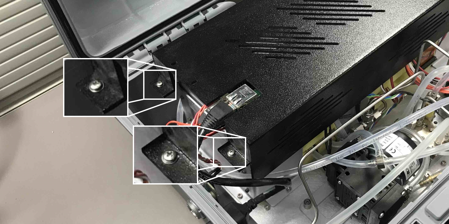
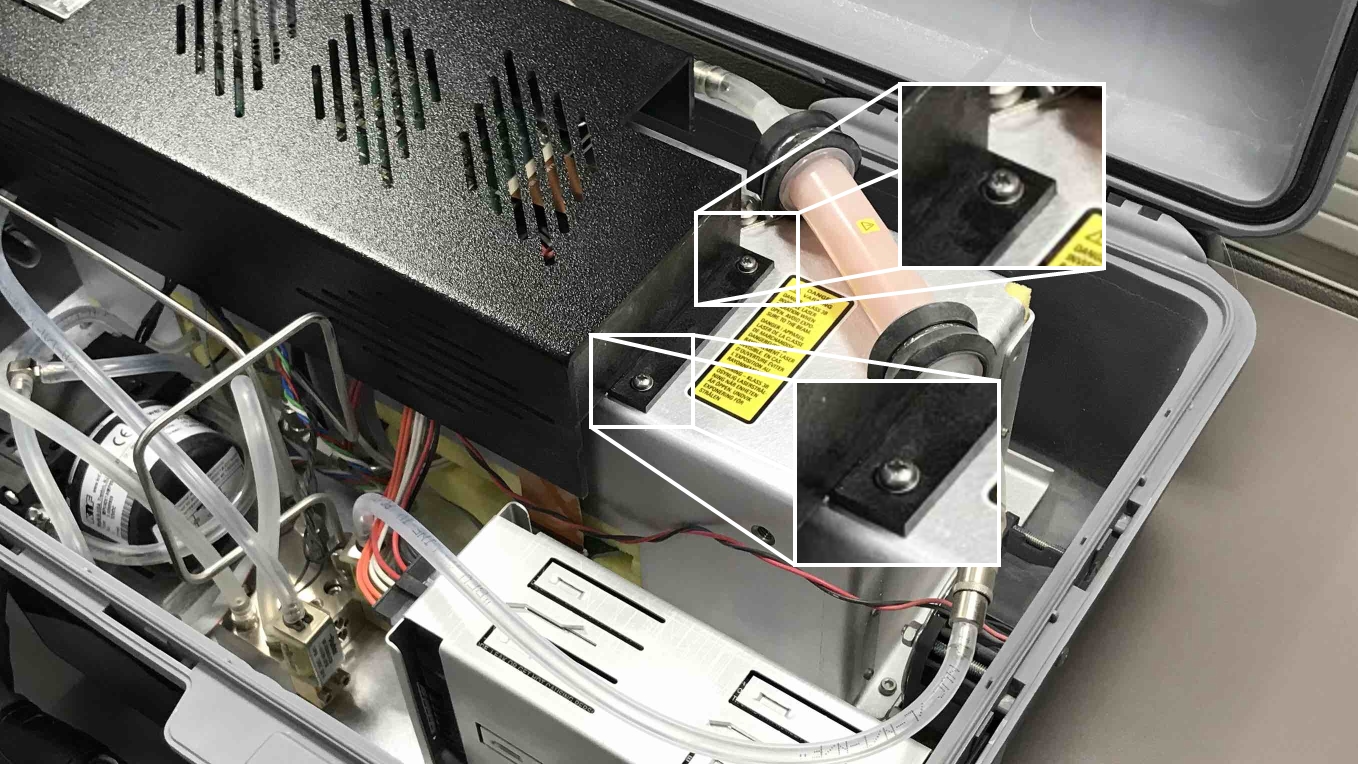
- Remove the four screws and washers that secure the electronics shroud.
- Do not move the shroud more than necessary because the internal Wi-Fi antenna can become disconnected. If you're careful, you won't have to reconnect it. If it does become disconnected, don't worry—you can reconnect it later.
- Carefully lift the front of the shroud, exposing the pump power cable connector.
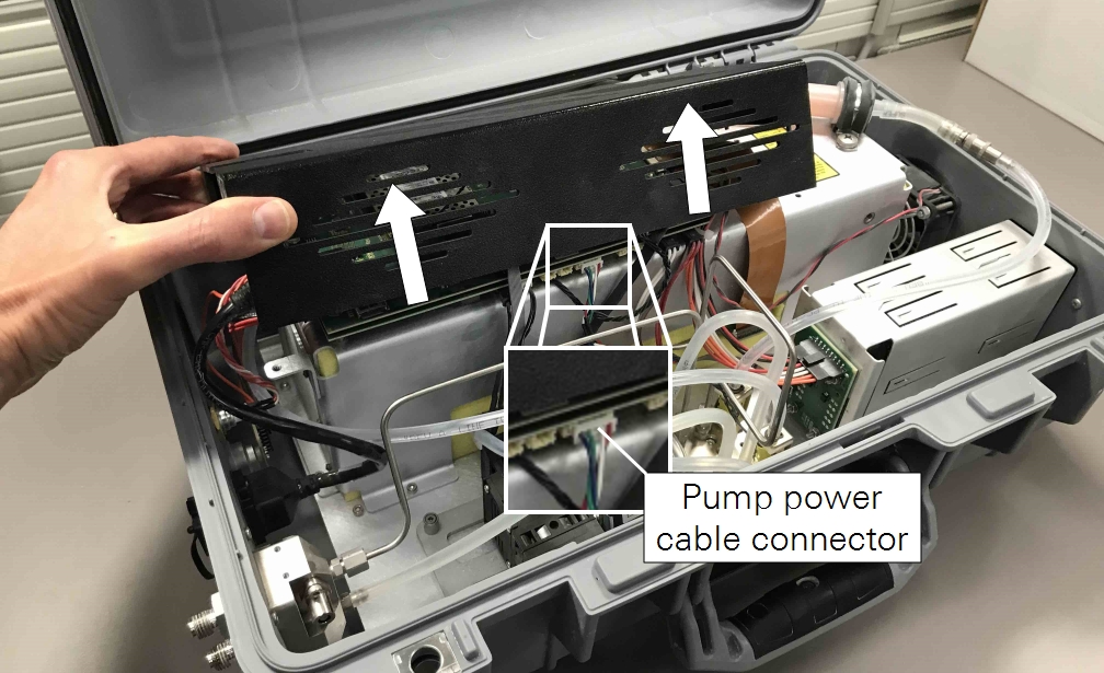
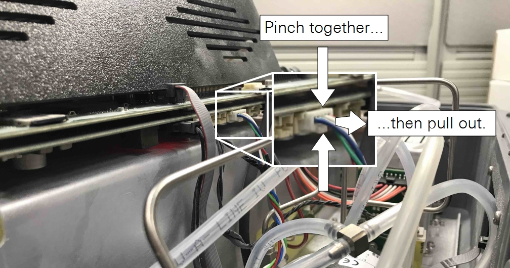
- Unplug the pump power cable connector.
- Pinch the clasp, then pull it free of the board. Be cautious while working near the stainless steel tubes. Avoid moving them around; doing so can cause leaks.
- Loosen the four screws that hold the pump in place.
- In early models, the pump is held by four non-captive screws. Be careful not to drop the screws in the case. Later models are equipped with captive screws.
- Loosen the screws completely and lift out the pump.
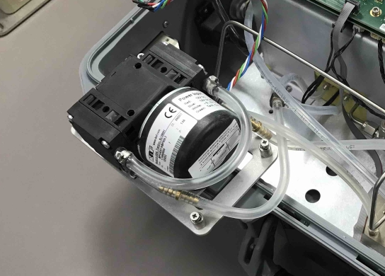
- Identify the two clear urethane tubes between brass couplings and the pump inlet and outlet.
- Cut both of the tubes. Leave enough tube on the hose barbs to grab with a pair of pliers.
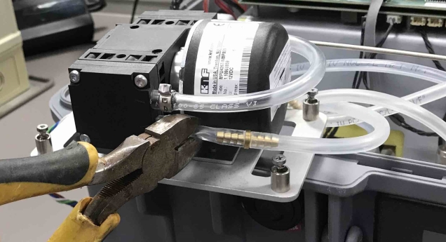
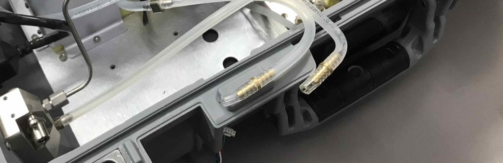
- Pull the remaining pieces of clear urethane tubing (not the translucent bev-a-line) off of each brass coupling.
- Grasp the coupling by the ring. Be careful to avoid damaging the barbs on the coupling. If a barb becomes scratched or nicked, replace it with a spare from the pump kit. A damaged barb can cause leaks.

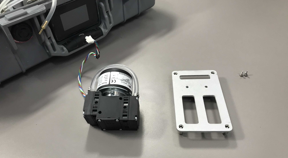
- Remove the pump mounting plate from the bottom of the pump.
- It is held on by two screws. They are treated with thread locking compound; you'll have to exert some effort to break them free.
The pump is free of the instrument.
Install the new pump
- Attach the pump to the bracket.
- Connect the tubing to the new pump.
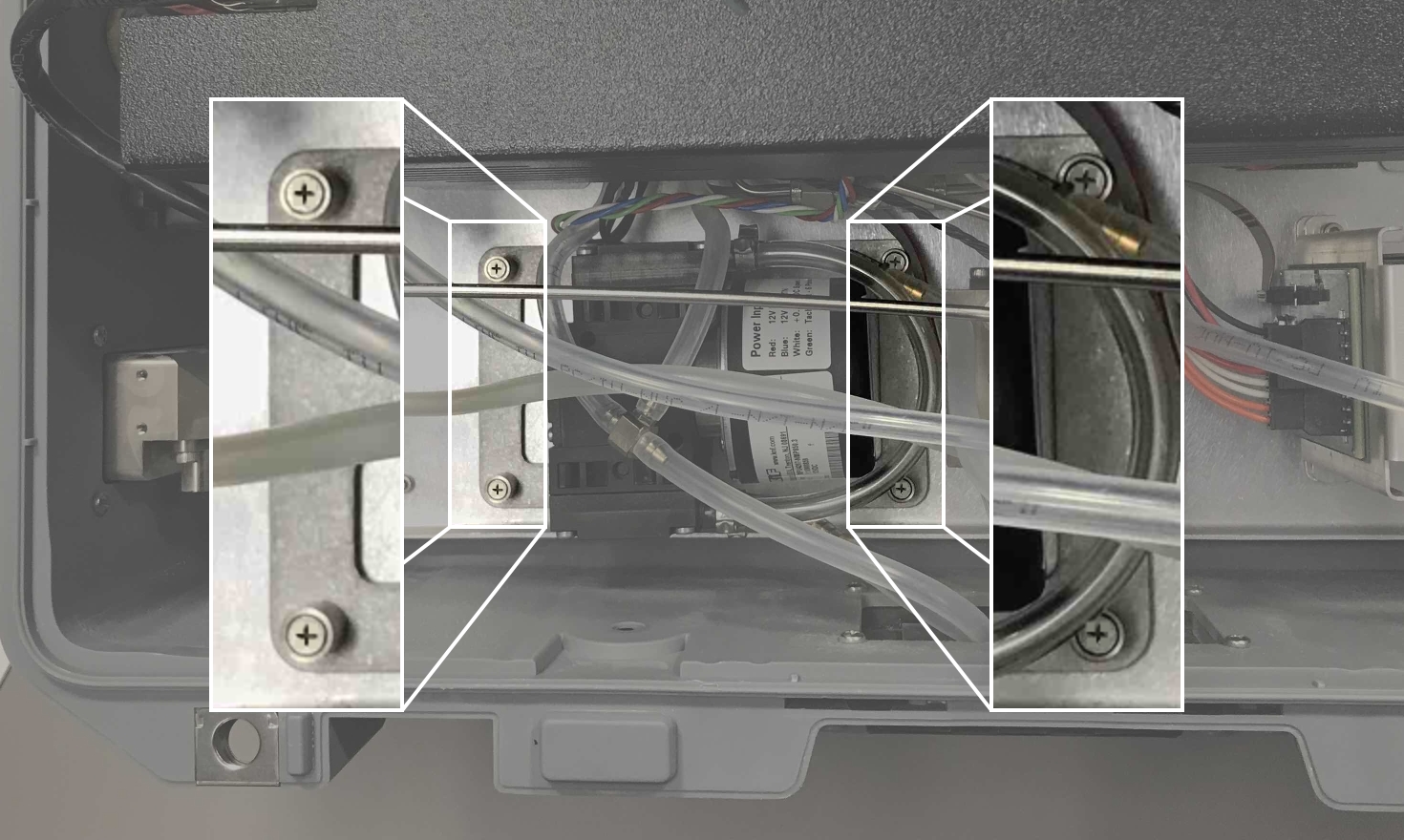
- Pay careful attention to the tube routing. If the tubes are not routed as shown, the pump will not fit in easily. The tubes should not be twisted or strained when reconnected. The pump inlet tube goes under the exhaust tube to the pump inlet.
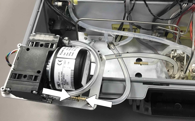
- The pump outlet tube goes under both the exhaust tube and the pump inlet tube to the pump outlet.

- Set the pump in place.
- Look carefully at the cable and tube routing. Be sure that none of the cables are pinched under the pump and that the tubes are not twisted. If tubes are twisted, the pump will not fit easily. The pump should fit in without requiring you to force anything into place.
- Tighten the four pump mounting screws.
-
- Reattach the pump power cable.
- It connects to the left-most of the two compatible connectors (the same one that is was removed from).
-
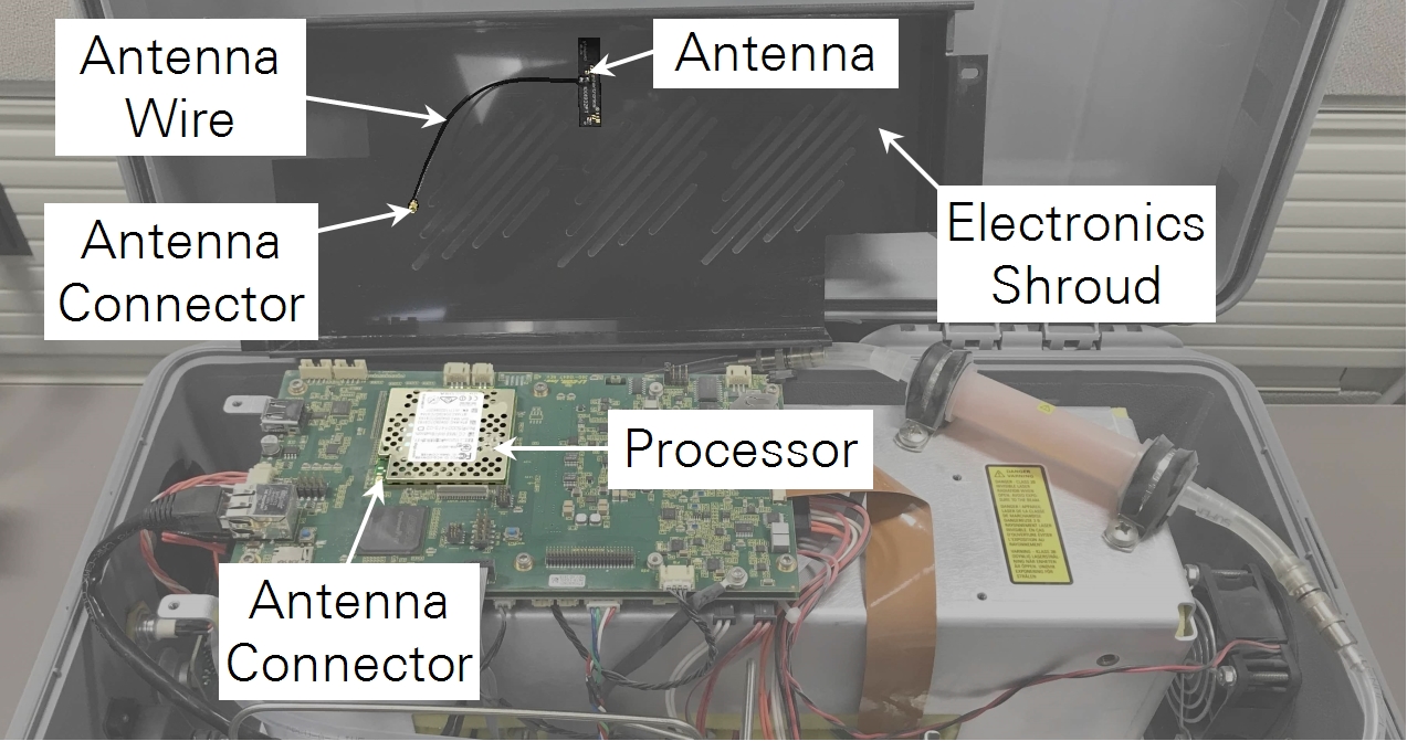
- Set the electronics shroud in place.
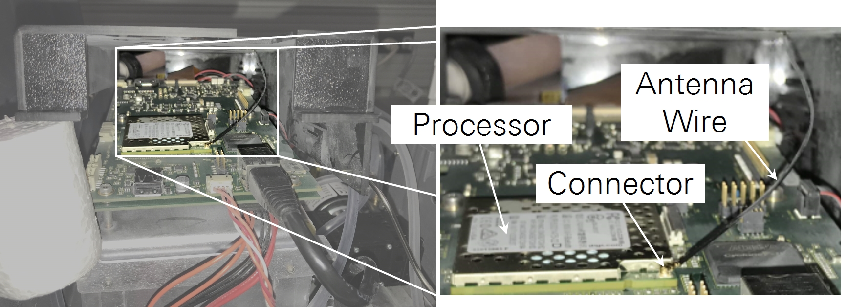
- Lift the left side of the shroud and look for the Wi-Fi antenna. It is a black insulated wire that is adhered to the underside of the shroud. It has a very small connector that attaches to a plug at a corner of the processor. If the antenna is unplugged, press it back onto the connector with your finger.
- Secure the shroud with four screws and washers.
- Tighten the screws snugly. Do not overtighten to avoid damaging the shroud.
Reset the pump hours
- Power on the instrument, let it warm up, and connect to it.
- Click Menu (
 ) > Settings (
 ) > Reset under pump operating hours.
The pump replacement is complete.