Using the reduced flow adapter kit
Printable PDF: Using the reduced flow adapter kit
(78xx_Reduced-Flow-Rate-Adapter-Kit_19053.pdf)
Download this content as a pdf that can be saved to your computer or printed.
The reduced flow rate adapter (part number 7800-112) is an accessory for the analyzer that, when installed, enables the LI-78xx series Trace Gas Analyzers to operate at a flow rate of 70 sccm, rather than the standard 250 sccm flow rate.
Components
The adapter assembly includes the following components. Everything is pre-assembled except for the two screws that secure the kit in the gas analyzer case.
| Description | Part # |
|---|---|
| Phillips Pan Head Screw M3×.5 6 mm (2) | 150-14477 |
| Phillips Pan Head Screw M6×8 mm (1) | 150-16920 |
| Air Filter (1) | 300-01961 |
| Angle Connector ¼" OD1 (1) | 300-03125 |
| Barbed Union (Brass) ⅛" ID2 (2) | 300-03761 |
| T-fitting with Barbs (Brass) ⅛" IDb (1) | 300-17724 |
| Flow Constrictor 0.006" Orifice ⅛" IDb (2) | 301-18700 |
| Stainless Steel Loop Clamp (1) | 342-17355 |
| Filter Mounting Bracket (1) | 9878-358 |
| Bev-a-line tubing | 222-01824 |
By installing the kit you will modify the internal flow routing of the instrument. When the kit is installed, you must use the Reduced Flow Rate option in the software. The reduced flow rate is not compatible with closed-loop applications because the inlet and outlet flow rate are different.
The kit is supported by instrument software version 2.0.25 and newer, which is available from licor.com/support/Trace-Gas-Analyzers/home.html (select an analyzer, then select software). All of these firmware updaters are the same; one can be used to update all Trace Gas Analyzer models.
Installing the kit
Power off the instrument before installing the kit.
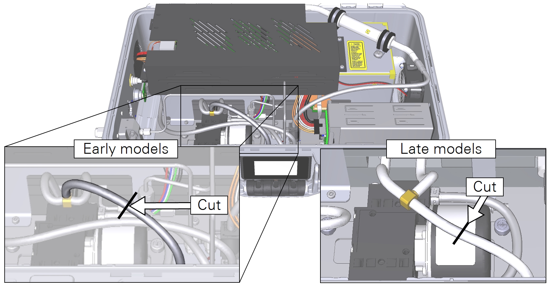
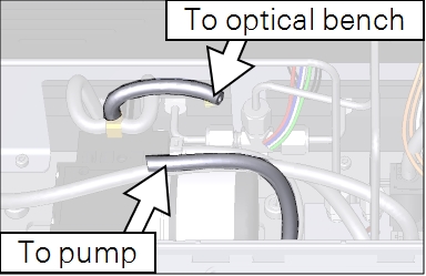
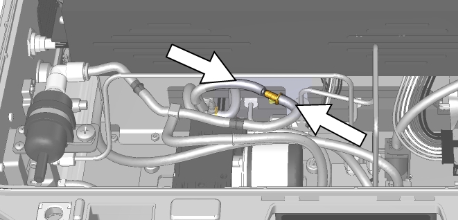
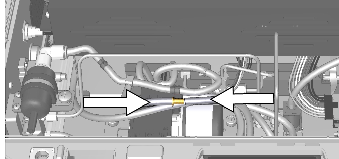
- Identify the tube that connects the pump to the optical bench.
- Pay careful attention to the orientation of the T-fitting. In early models, this tube comes off of the stem of the T. In later models, it comes off of the cross of the T. In either case, cut the tube with a clipper where indicated.
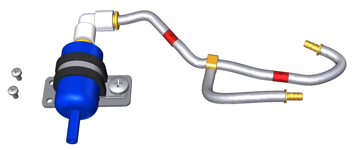
- Gather the kit and components.
- Secure the filter and tube assembly in the analyzer case with the two panhead screws.
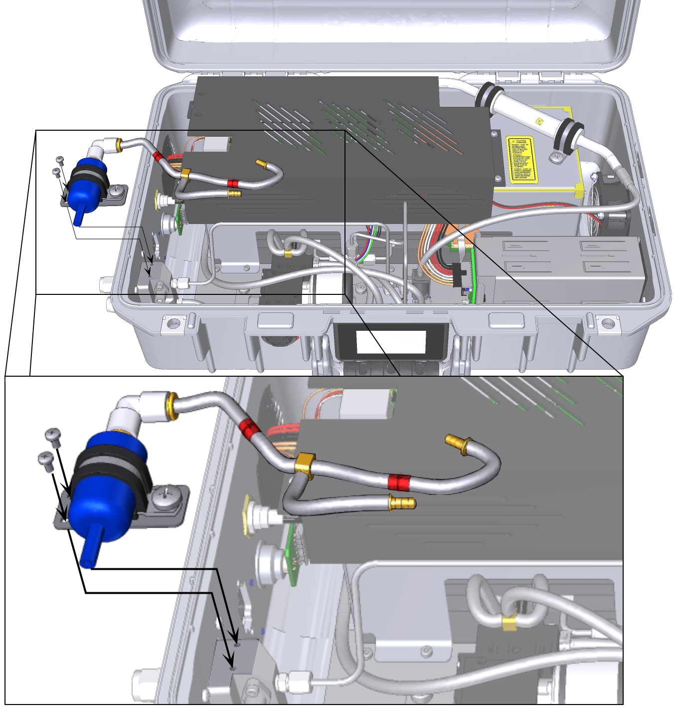
- The tubes will be straight before installation but they will easily bend to fit. They should go under the stainless steel tube air intake tube. Be careful to avoid jostling or moving the stainless steel tubes; moving them can cause leaks.
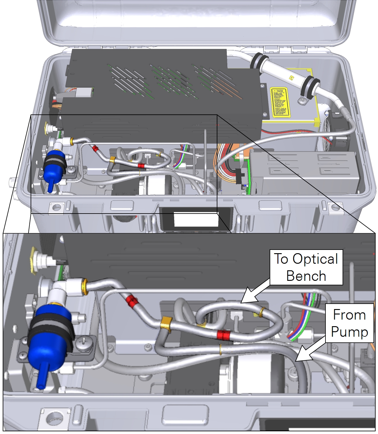
- For both tubes, press the hosebarb coupler into the cut tube, as shown.
- The completed assembly is shown below.
Configuring the software for the reduced flow kit
With new firmware, simply power on the instrument. The instrument will start up and operate with a flow rate of approximately 70 sccm.
Older TGA firmware has a setting that must be changed. Power on the instrument, let it warm up, and connect to it using a computer or mobile device. The instrument will start in the standard operating mode. Starting up in the standard mode while the Reduced Flow Rate Kit is installed will trigger warnings and errors; ignore them for now.
- Click Options > Settings > Software. Under Configuration, select Reduced Flow Rate.
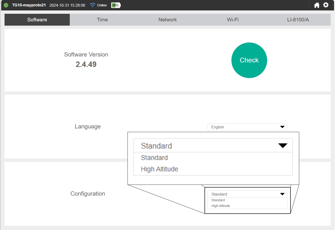
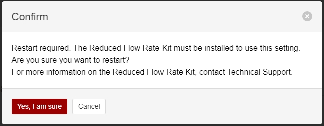
- When prompted, click Yes, I'm sure to proceed.
- The instrument will restart and initialize with the reduced flow rate configuration.
If you want to restore the normal flow rate, you must remove the reduced flow rate kit, change the instrument configuration to Standard and restart.
We do not recommend switching from one configuration to the other on a regular basis because the tubing is not designed for repeated assembly and disassembly.