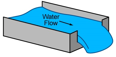
Water level and water flow channels
Note: This information applies to RXW-WL deployments created before March 18, 2026. Deployments created after this date already use the updated channel structure and will not require dashboard or export updates.
Updating dashboards and exports after the RXW-WL channel update
LI-CORCloud now separates the raw sensor measurement from the calculated water level for HOBOnet Water Level sensors (RXW-WL).
-
Sensor Depthrepresents the raw measurement reported by the sensor.
-
Water Levelrepresents the calculated water level, which may include reference level adjustments and user-defined scaling. This aligns the HOBOnet water level experience more closely with the RX2104 Water Level Station. Existing sensors continue logging data normally. Scaling, offsets, and labels remain unchanged.
After the update, a new export channel is created for the updated measurement definition. As a result:
-
Exports may include two columns representing historical and current measurements.
-
Dashboards referencing the previous channel may only display historical data until the updated channel is added.
Updating dashboards
Dashboards can be updated with the following steps:
-
Open the dashboard that displays RXW-WL water level data.
-
Edit the widget displaying the water level measurement.
-
Add the updated channel to the widget.
-
Save the widget.
If you want to visualize both historical and current measurements together, include both the previous channel and the updated channel in the widget (seeMerging datasets).
Updating exports
Data exports can be updated with the following steps:
-
Open your export configuration.
-
Confirm the existing water level measurement is present inExport Order.
-
Add the updated channel measurement toExport Order.
-
Save the export.
Setting up a water level channel
Note: Make sure the station has started logging and you have taken a reference water level reading from the location where the sensor is deployed with the date and time of the reading before performing these steps.
To set up a water level channel:
-
-
Select Water Level Sensors Logging.
-
Scroll down to Water Level and select Enable Channel.
-
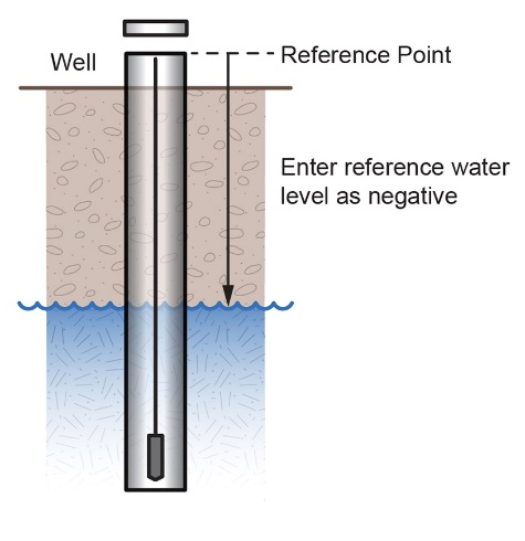
Enter the reference water level and date and time you took the reading.
-
If the water level surface is below the reference point as shown below, enter the reference water level as a negative number.
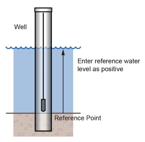
-
If the water level surface is above the reference point as shown below, enter the reference water level as a positive number.
-
- Select the water density that matches your deployment location.
- Click Save.
Water level is calculated starting with the next connection to LI-COR Cloud. Note that the reference water level information entered in this step does not affect any previously logged data. It is used only for data logged from the point of the next connection to LI-COR Cloud forward. If this is the first time that water level has been configured for this station, the data stored goes back to the date and time of the reference water level. If you make other updates to the reference water level, the data is updated only from the time of the next connection to LI-COR Cloud.
V-notch weir
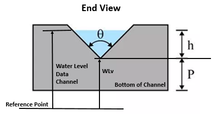
If you are using a v-notch weir similar to the upper diagram below along with the water level sensor, LI-COR Cloud can calculate the flow rate for each water level reading using the following two values that you enter:
-
The notch (vertex) angle in degrees or radians, which is represented as θ in the second diagram.
-
The distance from the reference point to the v-notch vertex, which is represented as WLv in the second diagram.
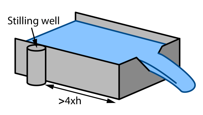
The LI-COR Cloud water flow calculations for a v-notch weir assume the following:
-
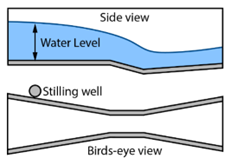
The stilling well with the water level sensor should be placed at a distance of at least 4 x hmax upstream of the weir.
-
In general, if the notch area is small relative to the area of the approach channel, the weir is “fully contracted” and these flow equations will work. More specifically, the ratio of the channel width to the v-notch width should be greater than 3, and the ratio of hmax/p should be less than 1. It may also work for weirs not meeting these guidelines if the approach channel is smooth, straight, and rectangular.
-
The weir should be between 0.8 and 2 mm (0.03 and 0.08 inches) thick in the v-notch. If the bulk of the weir is thicker than 2 mm (0.08 inches), the downstream edge of the v-notch can be chamfered at an angle greater than 45° (60° is recommended) to achieve the desired thickness of the edges. Avoid water clinging to the downstream face of the weir.
-
The head height (h) must be no more than 35% of the distance from the channel bottom to v-notch-vertex (P).
-
The head height must be at least 6 cm (2.36 inches). When the head height is less than 6 cm (2.36 inches), the flow calculation will not be as accurate.
-
The average width of the approach channel should be greater than 91 cm (3 ft).
-
The bottom of the v-notch should be at least 45 cm (1.5 ft) above the bottom of the upstream channel.
Caution: Make sure the station has started logging and you have configured the water level channel with a reference level reading before performing these steps.
To set up a water flow channel using a v-notch weir:
-
In LI-COR Cloud, select Devices and then click the wrench icon on your station’s tile.
-
Select Water Level Sensors Logging. Scroll down to Water Flow and select Enable Channel.
-
For the Measurement Method, select V-Notch Weir.
-
Enter the Notch Angle of the weir and select Degrees or Radians.
-
For Water level at vertex, enter the distance from the reference point to the v-notch vertex in meters (using the same reference point you used for the reference water level in the water level channel).
-
If the vertex is the reference point, enter 0.
-
If the reference point is the bottom of the channel, the value is represented as P in the diagram earlier in this section.
-
If the reference point is above the water level (such as when using ground level as the reference point in a storm sewer), enter a negative number.
-
If the reference point is below the water level, enter a positive number.
-
-
Click Save.
LI-COR Cloud calculates water flow starting with the next connection.
Tip: It is good practice to set an alarm for the water level just below the top of the v-notch so you know when the flow data is close to exceeding its valid range.
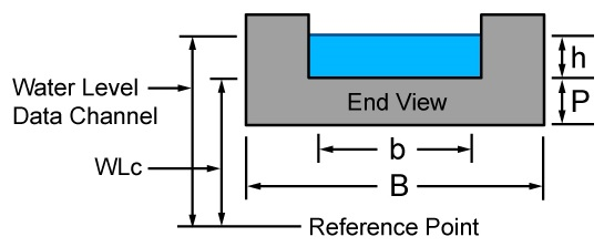
Rectangular weir
If you are using a rectangular thin-plate weir similar to the diagram below on the left along with the water level sensor, LI-COR Cloud can calculate the flow rate for each water level reading using four values that you enter.
Note: The units match what you select for reference water level units in the water level channel. The values are:
-
The notch width, which is represented as b in the second diagram.
-
The channel width, which is represented as B in the second diagram.
-
The notch height above the channel floor, which is represented as P in the second diagram.
-
The distance from the water level reference point to the notch crest, which is represented as WLc in the second diagram.
The LI-COR Cloud water flow calculations for a rectangular weir assume the following:
-
The range for the weir opening width is 0.15 to 6 m (0.5 to 20 ft).
-
The notch height (P) must be at least 0.1 m (0.33 ft).
-
Either B = b (full-width weir) or B - b must be at least 0.2 m (0.66 ft) (contracted weir).
-
The weir should be between 1 to 2 mm (0.03 to 0.08 inches) thick in the opening. If the bulk of the weir is thicker than 2 mm (0.08 inches), the downstream edge of the opening can be chamfered at an angle greater than 45° (60° is recommended) to achieve the desired thickness of the edges, and avoid water clinging to the downstream face of the weir.
-
The range for the head height (h) is 0.03 to 1.4 m (0.18 to 4.5 ft).
-
The range for the flow rate is from 3.45 to 17,188 l/s (0.122 to 607 ft3/s).
-
The value of h/p cannot be greater than 2.5.
-
Water surface downstream of the weir should be at least 0.06 cm (2.36 inches) below the weir crest (i.e. below the bottom of the opening).
Caution: Make sure the station has started logging and you have configured the water level channel with a reference level reading before performing these steps.
To set up a water flow channel using a rectangular weir:
-
In LI-COR Cloud, select Devices and then click the wrench icon on your station’s tile.
-
Select Water Level Sensors Logging.
-
Scroll down to Water Flow and select Enable Channel.
-
For the Measurement Method, select Rectangular Weir.
-
Enter the Notch Width.
-
Enter the Channel Width.
-
Enter the Notch Height Above Channel.
-
For the Distance from Water Level Ref Point to Notch, enter the distance from the reference point to the notch crest.
-
If the notch crest is the reference point, enter 0.
-
If the reference point is the bottom of the channel, the value is represented as P in the diagram earlier in this section.
-
If the reference point is above the water level (such as when using ground level as the reference point in a storm sewer), enter a negative number.
-
If the reference point is below the water level, enter a positive number.
-
- Click Save.
LI-COR Cloud calculates water flow starting with the next connection.
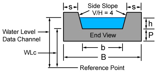
Trapezoidal weir
If you are using a trapezoidal or Cipoletti thin-plate weir similar to the one in the diagram below on the left along with the water level sensor, LI-COR Cloud can calculate the flow rate for each water level reading using two values that you enter. The values are:
-
The width at the base of the notch, which is represented as b in the second diagram.
-
The distance from the water level reference point to the notch crest, which is represented as WLc in the second diagram.
The LI-COR Cloud water flow calculations for a trapezoidal weir assume the following:
-
The slopes of the notch sides must be 4 (vertical change / horizontal change).
-
Head height (h) should be measured at a distance of at least 4 x hmax upstream of the weir.
-
The weir should be between 1 to 2 mm (0.04 to 0.08 inches) thick in the opening. If the bulk of the weir is thicker than 2 mm (0.08 inches), the downstream edge of the opening can be chamfered at an angle greater than 45° (60° is recommended) to achieve the desired thickness of the edges and avoid water clinging to the downstream face of the weir.
-
Water surface downstream of the weir should be at least 0.06 m (0.2 ft) below the weir crest (i.e., below the bottom of the opening).
-
The head height (h) must be at least 0.06 m (0.2 ft), but less than b/3.
-
The crest height above the channel floor (P) is measured from the bottom of the upstream channel and should be greater than 2 x hmax.
-
“S” is measured from the sides of the channel and should be greater than 2 x hmax.
Caution: Make sure the station has started logging and you have configured the water level channel with a reference level reading before performing these steps.
To set up a water flow channel using a trapezoidal weir:
-
In LI-COR Cloud, select Devices and then click the wrench icon on your station’s tile.
-
Select Water Level Sensors Logging.
-
Scroll down to Water Flow and select Enable Channel.
-
For the Measurement Method, select Trapezoidal Weir.
-
Enter the Notch Width at the bottom.
-
For the Distance from Water Level Ref Point to Notch, enter the distance from the reference point to the notch crest.
-
If the notch crest is the reference point, enter 0.
-
If the reference point is the bottom of the channel, the value is represented as P in the diagram earlier in this section.
-
If the reference point is above the water level (such as when using ground level as the reference point in a storm sewer), enter a negative number.
-
If the reference point is below the water level, enter a positive number.
-
- Click Save.
LI-COR Cloud calculates water flow starting with the next connection.
General flume
If you are using a flume along with the water level sensor, LI-COR Cloud can calculate the water flow using a general flow equation supported by a wide range of flumes that require only one water level measurement to calculate flow, including ramp, cutthroat, Parshall, as well as broad-crested rectangular weirs. The equation that LI-COR Cloud uses is: Water Flow (Q) = C * (Water Level - Head Offset)n. Flumes that require two or three water level measurements to calculate flow are not supported.
For this equation to be accurate, there are constraints on the flow conditions and flume design, including:
-
Minimum and maximum flow rates
-
Minimum and maximum head levels
-
Ratio of the width of the weir/flume to the head
-
Ratio of the height of the weir/flume to the head
-
Location in the flume or weir for measuring the head.
The constraints depend on the type and characteristics of the flume you are using, which can be obtained from the flume manufacturer.
Caution: Make sure the station has started logging and you have configured the water level channel with a reference level reading before performing these steps.
To set up a water flow channel using a general flume:
-
In LI-COR Cloud, select Devices and then click the wrench icon on your station’s tile.
-
Select Water Level Sensors Logging.
-
Scroll down to Water Flow and select Enable Channel.
-
For the Measurement Method, select General Flume.
-
For the Flume Coefficient, enter the C value listed in your flume’s equation table, which is typically found in the flume manufacturer’s documentation.
The Flume Coefficient may also be labeled K by some manufacturers so be sure to check how the coefficient is being used in their equation to make sure it is the right one to enter here.
-
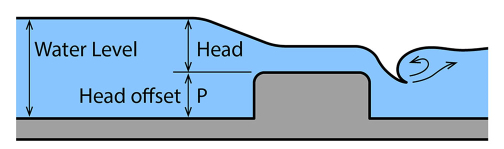
Enter the Head Offset. An example of Head Offset is shown in the following diagram of a ramp flume.
-
If you are using a ramp flume as shown in the diagram below and the top of the ramp is the reference point, enter 0.
-
If you are using a ramp flume and the bottom of the channel leading to the ramp (or crest) is the reference point, enter the height of the ramp or crest for the Head Offset (represented as P in the diagram).
-
For other types of flumes, such as this example diagram where the water level (or H) is being measured from the bottom of the flume:
-
If the bottom of the flume is the reference point for both the water level and head, enter 0 for the head offset.
-
If the reference point is above the water level (such as when using ground level as the reference point in a storm sewer), enter a negative number.
-
If the reference point is below the water level, enter a positive number.
- For the Head Exponent, enter the n value listed in your flume’s equation table, which is typically found in the flume manufacturer’s documentation.
- Click Save.
LI-COR Cloud calculates water flow starting with the next connection.
Stage-discharge table
You can set up a water flow channel that is calculated based on up to 20 stage-discharge points that you enter.
Before you begin setting up the channel, you must determine the values to enter into the stage-discharge table. LI-COR Cloud does not derive a stage discharge curve. Use another method to determine the stage-discharge curve for your site and enter points from that curve into the LI-COR Cloud stage-discharge table. LI-COR Cloud linearly interpolates between the points that you enter. You can estimate and enter intermediate points as needed to match your stage-discharge curve as closely as possible. LI-COR Cloud does not extrapolate beyond the lowest and highest stage values that you enter; make sure to enter values that span the full range of potential stage levels for your site, including flood conditions. Any measured water levels that are outside of the range you enter are shown as sensor errors (-888.88) for the water flow channel.
Follow these guidelines for getting a stage-discharge rating curve for your site:
-
If you are working with a USGS gaging site, you can use the USGS WaterWatch Customized Rating Curve Builder to get the rating curve for that site at https://waterwatch.usgs.gov/?id=mkrc.
-
If there is not an existing stage-discharge rating curve for your site, then you will need to build one. This requires measuring stage and discharge at multiple stage levels over time and then creating a stage-discharge curve. A good reference on measuring stage and discharge is at https://www.usgs.gov/special-topic/water-science-school/science/how-streamflow-measured.
Once you have enough stage and discharge measurements for your site, you can use those measurements to create the stage-discharge curve for the site. There are two common ways to do this:
-
Use a commercially available rating curve software tool, such as AQUARIUS or DataWise.
-
Create your own stage-discharge curve fit for your stage-discharge measurements with a spreadsheet, such as Excel, or with a statistical program, such as R. The most common equation used for stage-discharge curves is Manning’s Equation.
-
Once you have selected the type of equation to use, try different coefficients in the equation to determine which ones provide the best fit for your stage-discharge measurements.
-
Use the selected equation to determine a set of values to enter in the LI-COR Cloud stage-discharge table. If there are any levels at which there is a significant change in the stream profile, you must account for those as well. For example, when a stream overflows its banks, the stage-discharge relationship changes dramatically. The curve fit equation is no longer valid; you will need a different curve-fit equation for stage levels in this range.
-
-
Caution: Make sure the station has started logging and you have configured the water level channel with a reference level reading before performing these steps.
To set up a water flow channel using a stage discharge table:
-
In LI-COR Cloud, select Devices and then click the wrench icon on your station’s tile.
-
Select Water Level Sensors Logging. Scroll down to Water Flow and select Enable Channel.
-
For the Measurement Method, select Stage Discharge Table.
-
Enter each pair of stage-discharge points. Click Add A Row to add up to 20 pairs of points.
-
Click Save.
LI-COR Cloud calculates water flow starting with the next connection.