Logging LI-710 Data to a Campbell Scientific Datalogger
Authors: LI-COR, Inc.
Correspondence: envsupport@licor.com
Published: 2022
Instruments: LI-710
Keywords: evapotranspiration, logging data, datalogger, CR1000, CR300, CR5000
Abstract
You can record data from the LI-710 on Campbell Scientific® dataloggers that support the SDI-12 protocol. This tutorial provides the steps and simple programs for connecting the LI-710 to a CR1000X, CR1000, CR300, CR6, or CR5000 datalogger. The programs described here will read data from the LI-710 only.
Requirements for this tutorial
The following items are required to complete this tutorial.


- LI-710 Evapotranspiration Sensor.
- Datalogger programs for the logging LI-710 data to a Campbell Scientific datalogger
- 1-minute programs for testing: licor.app.boxenterprise.net/s/8nn23rrx6ymon8ieljbv17aelvbzrgov.
- 30-minute programs for deployment: licor.app.boxenterprise.net/s/ms47kjmoprha9jphpw010aumhtsumv2b
- Personal Computer (Windows OS).
- Campbell Scientific datalogger: CR1000X, CR1000, CR6, or CR5000.
- PC400 software from Campbell Scientific, Inc. The software is available from campbellsci.com/downloads/pc400. This tutorial describes version 4.7.
Wire assignments
The LI-710 is powered over the brown wire (9 to 33 VDC). Data are transferred over the blue DATA wire. The black wire connects to ground. Some SDI-12 power supplies do not provide enough current to power up the LI-710. If you observe continuous power cycling, consider powering the LI-710 directly from the data logger power supply.

Default address
All LI-710s leave LI-COR with an address of 0. The address can be changed with the A command. Multiple LI-710s can be connected to a single SDI-12 bus, but each LI-710 requires a unique address.
The trigger command
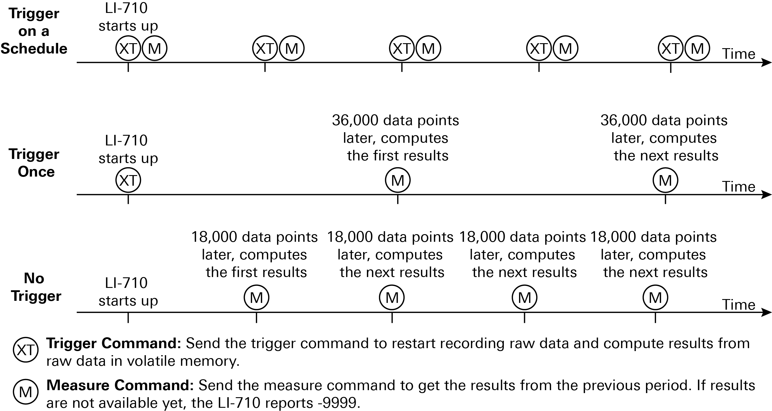
The LI-710 is designed to respond to trigger (XT) commands on a schedule. Trigger options and the expected results are described below.
Trigger on a schedule with the XT command
Note: We recommend Trigger on a schedule for deployments. In this mode, the datalogger sends the XT command to start a measurement period and the M command to request results from the previous period. This gives you control over the measurement time period and aligns results to the datalogger clock.
In triggered mode, the LI-710 starts up and begins recording raw data to its volatile memory. When the LI-710 receives an XT command, it computes results from data in the volatile memory and starts recording new raw data to the volatile memory. These results are reported in response to an M command until new results are available – a few seconds after the LI-710 receives another XT command (see Trigger on a schedule in Figure 3).
We recommend sending the XT command every 30 minutes, but you can choose any time period between 5 and 60 minutes. The time period for computing results is defined by the time period between XT commands sent by the datalogger.
Trigger once
Note: Trigger once is for testing or a fallback if the trigger is not received.
If the LI-710 receives an XT command but does not receive another, it will compute results when it has recorded 36,000 data points, which is around one hour (see Trigger once in Figure 3). If triggered only once, the subsequent measurements will gradually drift from the datalogger clock.
No trigger
Note: Use No trigger for testing only.
The LI-710 operates in untriggered mode unless it receives a trigger command. In untriggered mode, the measurement period does not have explicit alignment with a clock. Instead, the LI-710 begins recording raw data to its volatile memory almost immediately after it is powered on. After it has recorded 18,000 data points (about 30 minutes of data), it computes results for that time period. These results are reported until the next results are ready 18,000 data points later (see No trigger in Figure 3).
Common commands
The following commands are supported by the LI-710.
- ? – get the sensor address
- I - get sensor information
- A – set the sensor address
- M – report current measurements
- XT – trigger to start a new measurement period.
Measurement settings
Send the LI-710 the M command to collect data and the XT command to trigger a new measurement period. M0 collects the basic data set. M1, M2, or M3 collect different data sets. The contents of each packet that is returned by the M commands are defined in the LI-710 instruction manual.
Configuring the datalogger
Follow these steps to connect an LI-710 to the datalogger.
- Connect the LI-710 to the datalogger terminals.
- The terminals must provide power (12 VDC), ground, and a data connection. In this example, we use terminal C1, which is labeled on the logger and specified in the program as the SDI-12 terminal for this sensor.
-

Figure 4. The LI-710 connects to a 12 VDC power supply (brown), ground (black), and an SDI-12 terminal (blue to C1 in this example). - Power on the datalogger.
- The datalogger will power on when power is supplied.
- Connect a communication cable between the datalogger and your computer.
- We use the USB connection on the CR1000X for this tutorial.
- You may need to use the serial or Ethernet connection with dataloggers that do not support USB. In any case, the steps are the same after you have established communication between your PC and the datalogger.
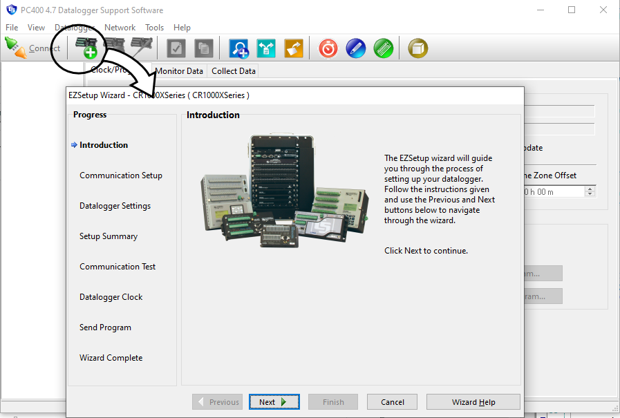
- Launch the PC400 application.
- If you've configured the connection already, just connect to the datalogger and go to the next step.
- If it is the first time you've connected, add a datalogger to the list and configure the settings.
- Select the datalogger model and assign a name.
- Select Direct Connection as the type.
- Select a COM port number (if it is the first time connecting, install the device driver now).
- Click through the remaining prompts, leaving the default settings as they are or making changes to suit yourself. You could send a program to the datalogger in the Wizard, but there are some other settings to check and configure before doing so.
- Consider the LI-710 SDI-12 address.
- Each LI-710 has an SDI-12 address of 0 by default. The sample programs use an address of 0 as well, and are compatible with the LI-710 in its default configuration. If you need to change the sensor address, we describe that in Trigger on a schedule with the XT command. If you change the address, you must also modify the program as well (you can do this easily in a text editor).
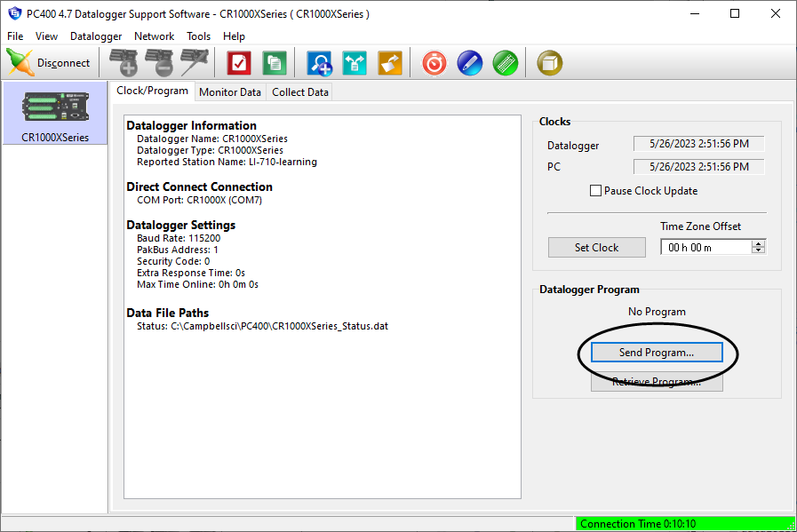
- Click Send Program to send the program to the datalogger.
- For testing, we provide a program that records measurements every one minute. The program you use in deployments records measurements every 30 minutes; we provide those too.
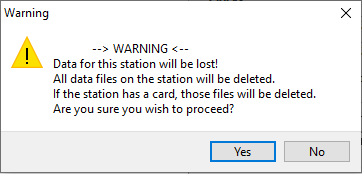
- Click Yes to dismiss the warning; allow the logger to compile the program.
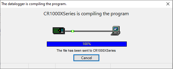
- The datalogger will restart; reconnect after it restarts.
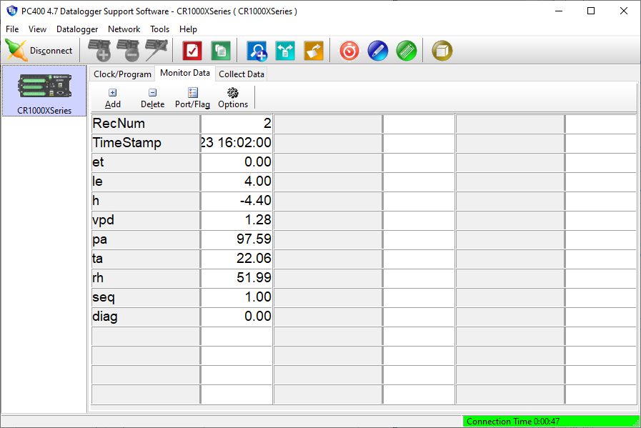
- Click Monitor Data to view the latest results.
Retrieving logged data
The datalogger stores the readings to its internal memory. To copy the data to your computer:
- Click Start Data Collection to save the logged data to a file on your computer.
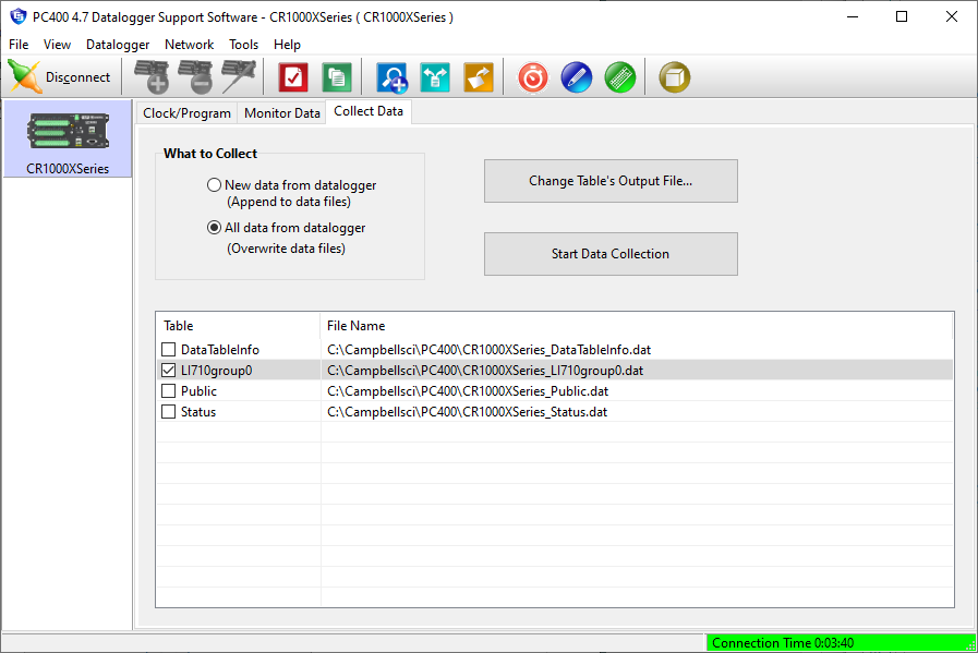
- Select an output file and click OK.
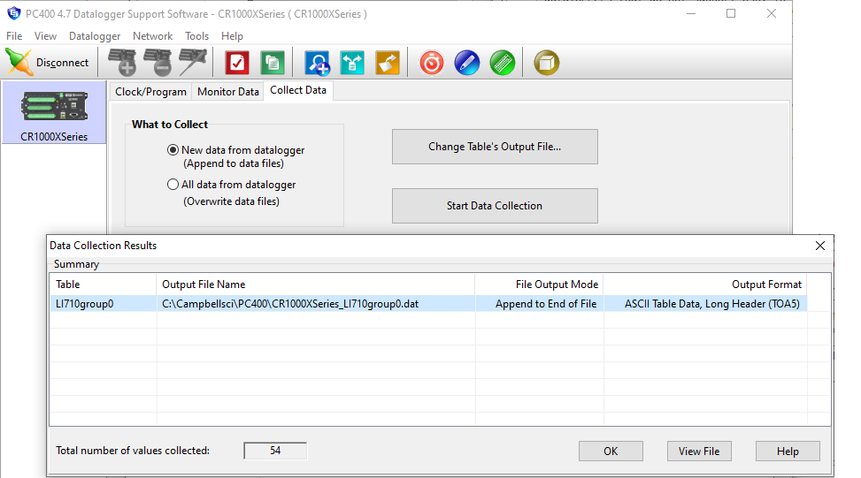
- The directory is indicated in the column called Output File Name.
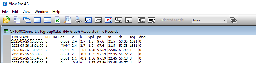
- Click View File to see the records saved so far.
The PC400 terminal program
The PC400 has a built-in terminal emulator that you can use to communicate with the LI-710. To use it, connect with the datalogger as described earlier and follow these steps:
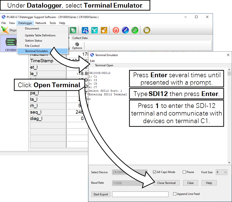
- In PC400, click Datalogger > Terminal Emulator.
- In the new window, click the Open Terminal button and then click in the terminal to bring focus to that window.
- Press Enter one or more times to get a response from the datalogger.
- The response will be something like
CR1000X>. - Type SDI12 and press Enter.
- When presented the menu, select the port (press 1 if your LI-710 is on terminal C1).
- Now you can query the LI-710 with the following commands:
Get the address
- Command ?!
- Reply:
0(or whatever the address is)
Set the address
To change the address from 0 to 1
- Command: 0A1!
- Reply:
1
Note: If you change the address, you must modify the address in the program to match the sensor's address.
Get information
- Command: 0I! (the number zero, the capital letter I for information, ending with an exclamation point).
- Reply:
014LI-COR LI-7101.0ET100033(identifying information for the sensor, including the device address, manufacturer, model, firmware version, and serial number).
Read current data from a group
The command to read data.
- Command: 0R0!
- Reply:
0+0.00+0.02+0.02+1.39+97.55+22.47+48.87+0 - Command: 0R1!
- Reply:
1+0.00+0.02+0.02+97.55+22.47+48.87+600+0
The two examples show data group 0 and data group 1. Enter 2 or 3 in place of the 0 or 1 to read those data groups.
Simple program with comments
The program in Listing 1 is for a Campbell Scientific CR1000X, CR1000, CR5000, or CR6 Datalogger. This example includes comments to show you which parameters can be modified.
Listing 1. A program for Campbell Scientific, Inc. CR1000X, CR1000, CR5000, or CR6 datalogger.
'LI-710 simple logger
'Rev: 0.1
'Date: May 23, 2023
'Author: licor.com

Public LI710A(9) 'names an array and specifies that it has 9 variables
Alias LI710A(1)=et_l 'the first of 9
Units et_l=mm
Alias LI710A(2)=le_l
Units le_l=W/M^2
Alias LI710A(3)=h_l
Units h_l=W/M^2
Alias LI710A(4)=vpd_l
Units vpd_l=kPa
Alias LI710A(5)=pa_l
Units pa_l=kPa
Alias LI710A(6)=ta_l
Units ta_l=C
Alias LI710A(7)=rh_l
Units rh_l=%
Alias LI710A(8)=seq_l
Units seq_l=count
Alias LI710A(9)=diag_l
Units diag_l=Dimensionless

DataTable (LI710group0,True,-1) 'creates and names a data table
    DataInterval(0,30,Min,10) 'specifies the interval for writing to the table
    Sample(9,LI710A,IEEE4)
EndTable

BeginProg
  Scan (30,Min,1,0) 'specifies the interval for scanning for new data
    SDI12Recorder(LI710A,C1,0,"XT!",1.0,0) 'instructs the SDI-12 device on terminal C1 to start sampling
    SDI12Recorder(LI710A,C1,0,"M0!",1.0,0) 'requests group 0 (M0) from the SDI-12 device on terminal C1
    CallTable LI710group0
  NextScan
Installation options
Horizontal cross bar
The LI-710 can be attached to a standard ¾" crossover fitting or any other fitting with a 1" opening. Suitable crossover fittings (¾" × 1") are available from LI-COR (part number 259-13276).

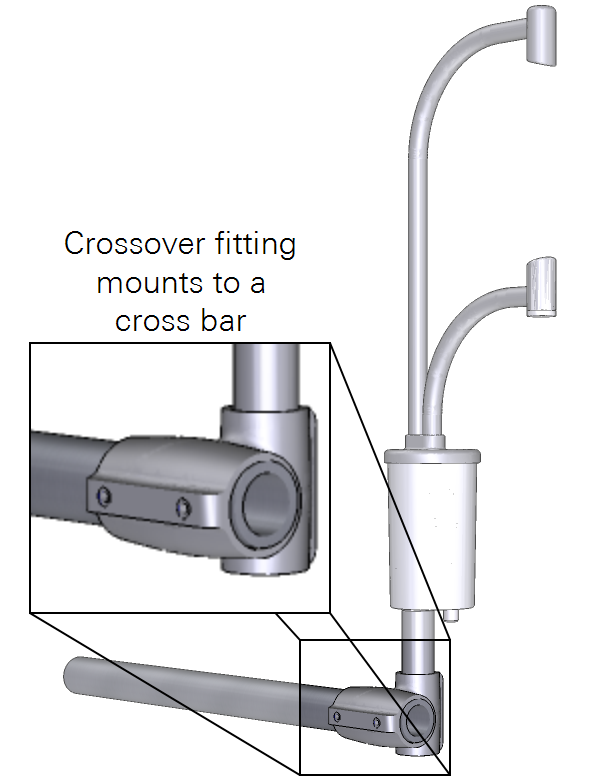
Tighten set screws with a 5/32" hex key to 22 N-m (16 ft-lbs). If no torque wrench is available, tighten each set screw until it contacts the pipe, then one more full revolution for aluminum pipe, or ¼ revolution for stainless steel.
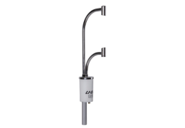
Vertical pipe and T-post
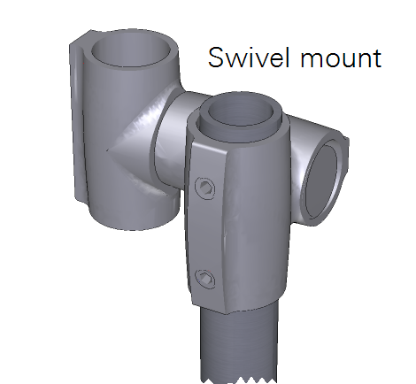
For a stand-alone installation, the LI-710 can be attached to a T-post and vertical mast, like a piece of pipe. The LI-710 can attach to a pipe using a swivel mount, or the post can be installed inside a pipe that has an inside diameter >1 inch (2.54 cm) and a means to secure the post (Figure 6).

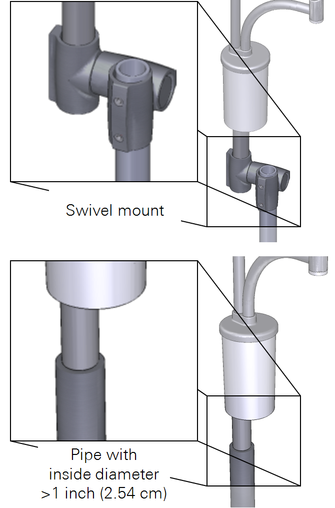
If you are using a T-post in soft or saturated soils, check the installation regularly to ensure that the post does not shift over time.