7550-101 Auxiliary Sensor Interface
The optional Auxiliary Sensor Interface (ASI) is an O-ring sealed, weatherproof junction box that can be used to connect analog inputs and/or outputs. It has connections for up to six analog outputs, four general purpose analog inputs, and a constant 5 VDC source (5 mA maximum).
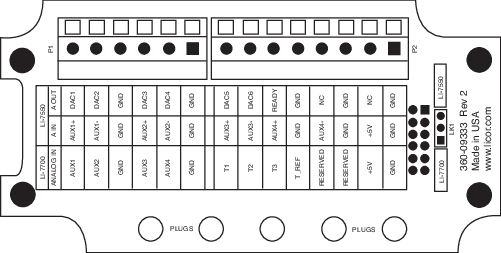
The ASI can also be configured to work with the LI-7700 Open Path CH4 Analyzer. There is a small jumper located at position LK1 (far right in Figure B‑1). When using the ASI with the LI-7700, make sure that the jumper is positioned over the 2 pins nearest the LI-7550 label (the topmost 2 pins).
Mounting the ASI
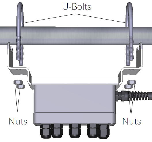
The ASI mounting bracket can be attached to a 1 to 1½” (2.5 to 4 cm) post. Two U-bolts and hex nuts are included for this purpose. It can be mounted either vertically or horizontally, but to prevent leaks, orient the plugs so they face the ground. If you do not want to use the mounting plate, remove the two screws that hold the mounting bracket and secure it however you want.
Terminal connections
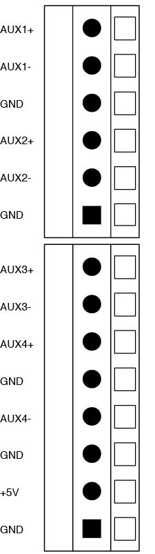
Terminal positions for analog inputs are:
| Terminal | Analog Inputs1 | Description | |
|---|---|---|---|
|
1 | AUX1+ | Auxiliary Input 1 positive |
| 2 | AUX1- | Auxiliary Input 1 negative | |
| 3 | GND | Ground | |
| 4 | AUX2+ | Auxiliary Input 2 positive | |
| 5 | AUX2- | Auxiliary Input 2 negative | |
| 6 | GND | Ground | |
| 7 | AUX3+ | Auxiliary Input 3 positive | |
| 8 | AUX3- | Auxiliary Input 3 negative | |
| 9 | AUX4+ | Auxiliary Input 4 positive | |
| 10 | GND | Ground | |
| 11 | AUX4- | Auxiliary Input 4 negative | |
| 12 | GND | Ground | |
| 13 | +5V | +5V supply | |
| 14 | GND | Ground |
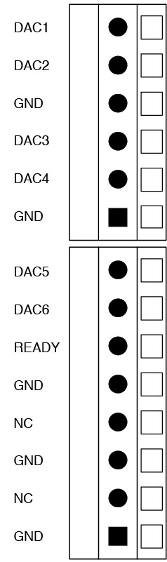
Terminal positions for analog outputs are:
| Terminal | Analog Outputs2 | Description | |
|---|---|---|---|
|
1 | DAC1 | DAC channel 1 positive |
| 2 | DAC2 | DAC channel 2 positive | |
| 3 | GND | Ground | |
| 4 | DAC3 | DAC channel 3 positive | |
| 5 | DAC4 | DAC channel 4 positive | |
| 6 | GND | Ground | |
| 7 | DAC5 | DAC channel 5 positive | |
| 8 | DAC6 | DAC channel 6 positive | |
| 9 | READY | Analyzer ready | |
| 10 | GND | Ground | |
| 11 | NC | No connection | |
| 12 | GND | Ground | |
| 13 | NC | No connection | |
| 14 | GND | Ground |
Electrical connections
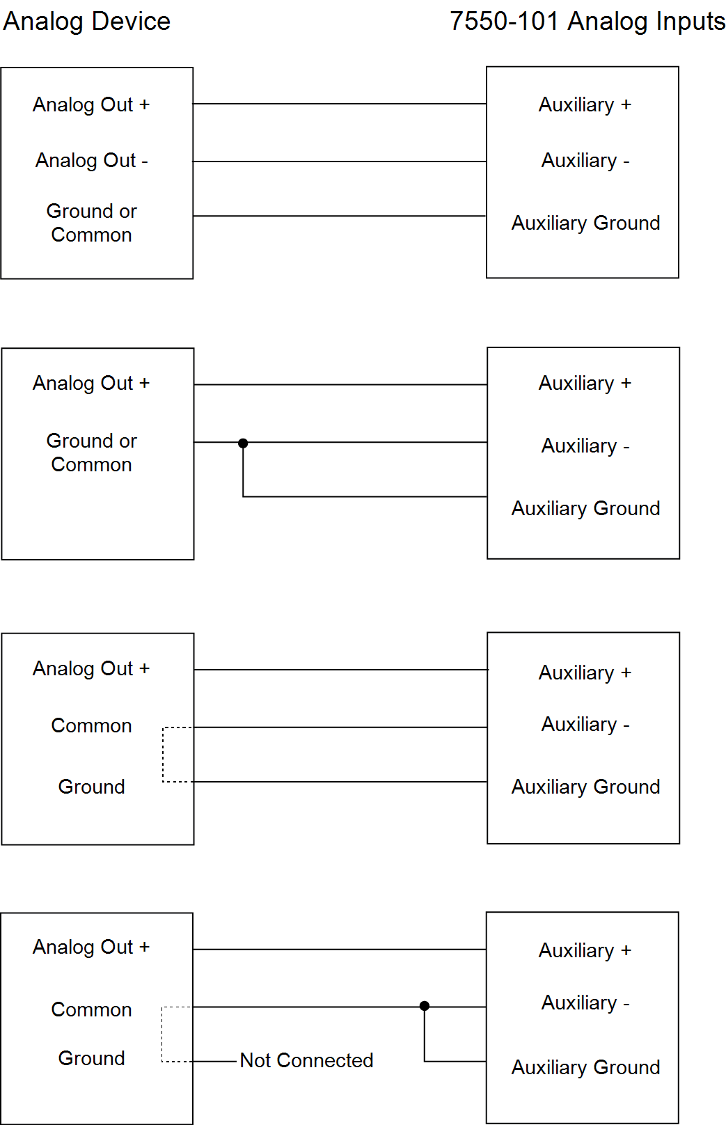
All analog devices connected to the ASI must be referenced to the ground (GND) connection; some examples are shown below.
- All auxiliary analog input ground connections are internally connected together.
- All auxiliary analog output ground connections are internally connected together.
- Analog devices with both ground and common outputs can share these outputs with their power supply ground.
- LI-7550 analog inputs are electrically isolated from the LI-7550 power input.
- LI-7550 analog outputs are electrically isolated from the LI-7550 power input and isolated from the analog inputs.
Connecting sensors
There are gland plugs on the ASI top cover, through which the sensor wires pass, after which they are connected to the appropriate screw terminals. Follow these steps to attach sensors or power to the ASI:
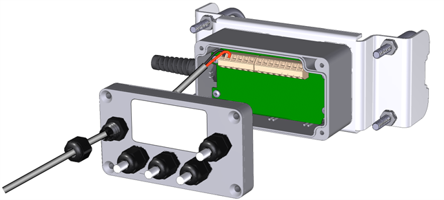
- Remove the Philips screws from the corners of the ASI and remove the top cover.
- Remove the cap from a gland plug.
- Pass the wires through the cap and then through the gland plug.
- Insert the wire leads into the appropriate terminals. Tighten the terminals to secure the wires.
- Make a note of which plug the wires are passing through (e.g., A, B, C), and to which terminals the wires are connected. This information will be needed when you enter the sensor calibration coefficients into software.
- Pull gently on the wires to remove excess wire from inside the interface. Re-attach the interface top cover and tighten the gland plug cap.
- Attach the ASI cable connector to the ANALOG IN connection on the Analyzer Interface Unit.
There are 5 EPDM type plugs inside the box that can be inserted into unused gland plugs. The plugs prevent water, insects, and dirt from entering the interface box. Remove the top cover and insert the narrow end of the plug through the back of the gland plug(s) and tighten the plug cap(s). The plugs should be used any time there are gland plugs that do not have wires inserted through them.
There is a length of Santoprene tubing in the ASI spares kit. This tubing can be cut to length and placed around small gauge wires that may not be able to be tightened sufficiently with the gland plug caps. It can also be used for oddly shaped wires that can be difficult to seal with the gland plug caps.