This section provides basic operating instructions for the LI-8810 AtmospherIQ CH4/CO2/H2O Gas Analyzer.
Unpack the analyzer, removing the protective foam. Keep the packing materials so you can ship the analyzer in the future.
Rack or cabinet mounts
AtmospherIQ gas analyzers fit into an instrument rack or cabinet with a 19" (48.26 cm) opening. Each analyzer will occupy four rack units (4U). The analyzer includes slide rails. To install rails, refer to the instruction sheet and these steps:
-
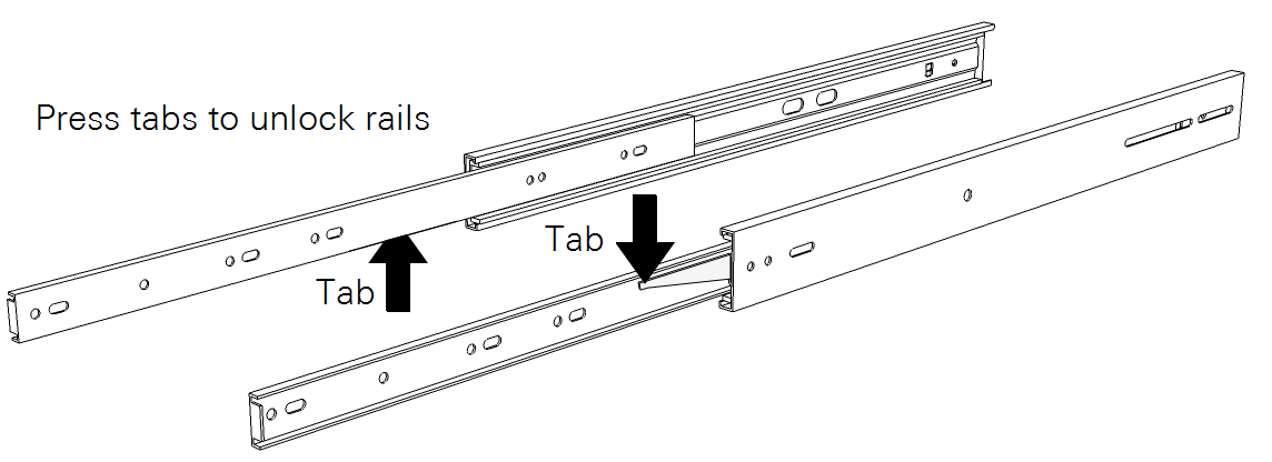
Separate the rail sliders.
Each slider has a tab that you press to unlock the two parts. The smaller slider mounts to the analyzer; the larger one mounts to the rack.
-
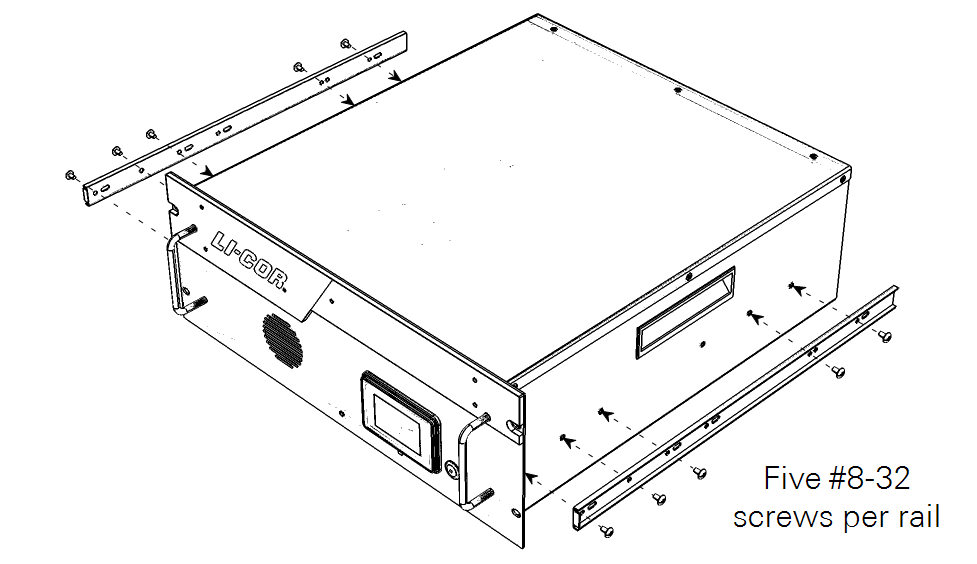
Attach the small slide rails to the analyzer with five 8-32 button-head machine screws each.
-
Install the rack sliders in the rack.
Racks vary, and yours may be different from what is described here. Choose the hardware that is compatible with your rack. The analyzer and the rails that support it should be secured at the front and back.
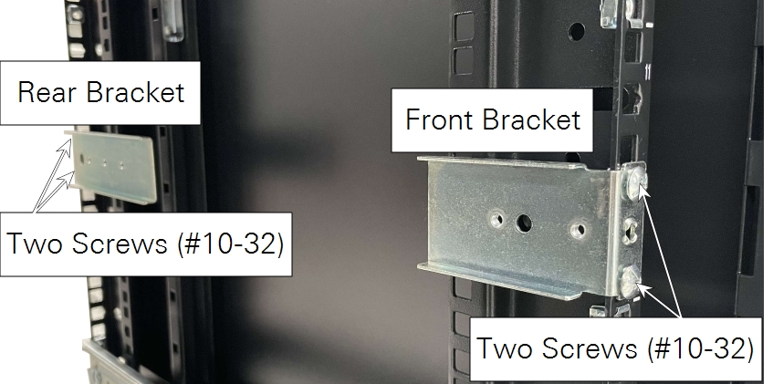
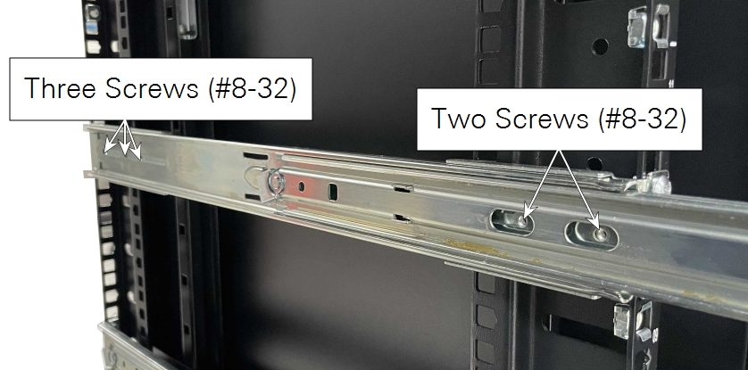
Figure 2‑1. Rails attach to the rack with brackets and screws at the front (left) and back (right). Instrument racks vary; install the rails using the best method for your rack. -
Lift the analyzer into position and slide it onto the rack rails.

Lift the instrument using the handles on the sides. The unit weighs over 18 kg (40 lbs). Use good lifting posture, and get help if you are unable to lift the instrument by yourself.
-
Check the installation to be sure the analyzer is secure in the rack.
Caution: Do not mount the analyzer with the front panel only. If installing in a rack with different hardware, additional bracing may be required. Be sure the front and back are supported in the rack.
Attaching tubes to the air inlet and outlet
Air is drawn into the sample cell through the air inlet. Connect tubing to the inlet with the nut, bushing, and ferrule from the accessories kit. Optional stainless steel inserts (300-18126) are included for use with soft tubing. Tubing can be connected to the inlet and the outlet in the same way.
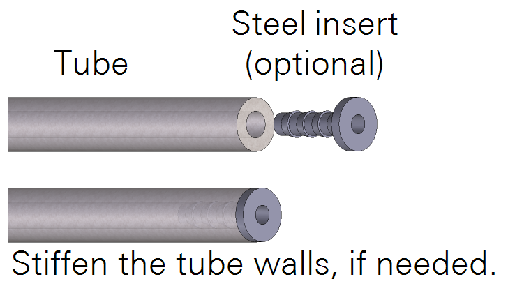
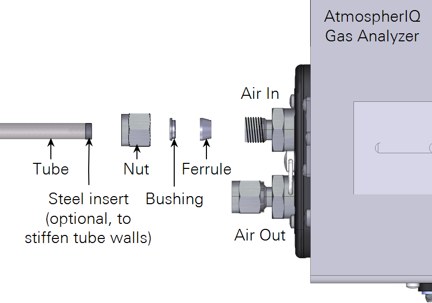
To connect a ¼" outside-diameter metal or plastic tube to the compression fitting, insert the nut, bushing, and ferrule over the tube. Then tighten the nut over the ferrule until it is finger tight. Tighten it an additional 1-¼ revolutions if you are connecting the tube for the first time. For highly pliable plastic tubing, place a stainless steel tube insert (300-18126) inside the tubing to make it rigid enough.
When reconnecting a plastic or metal tube that has been connected previously, simply tighten it ¼ turn beyond finger tight.
Caution: Abrupt pressure transients up to 35 kPa above or below ambient pressure may cause momentary status warnings, inlet plugged warnings, and measurement inaccuracies. Longer lasting pressure excursions or larger pressure transients may cause the instrument to reinitialize measurement control loops.
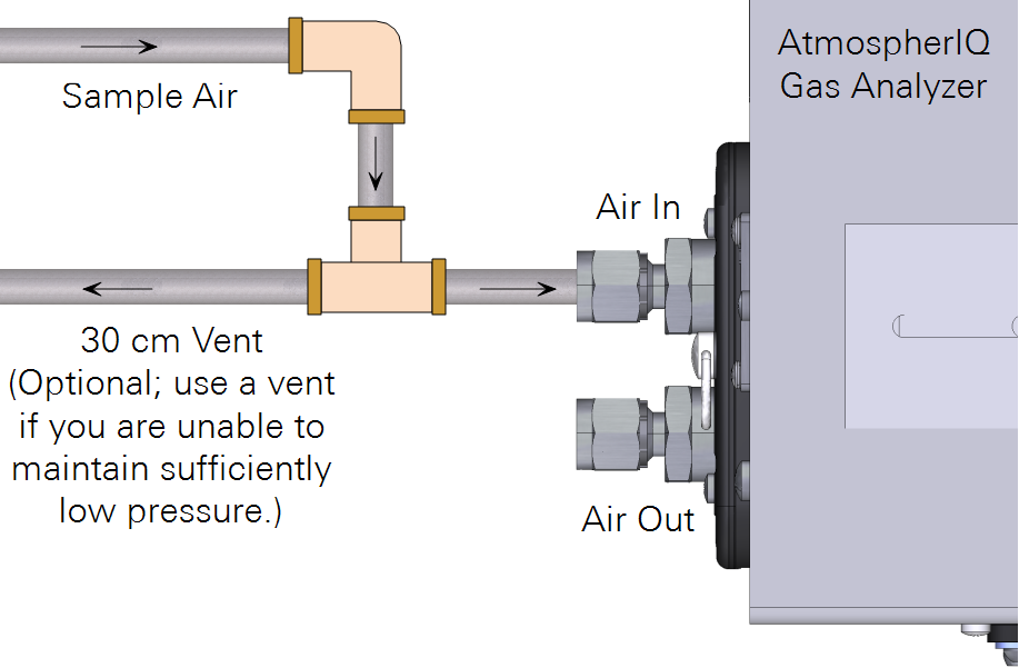
A typical sampling application will use the LI-8810 to subsample a gas from a main sample line. Air passes a single time through the gas analyzer before it is discharged. Air supplied to the sample inlet should be between ambient and 35 kPa (5 PSI) above ambient. If the pressure is higher than that, install a 30 cm vent in the sample line to ensure that air from the external pump does not pressurize the analyzer. The vent must be sufficiently long to prevent diffusion of ambient air into the sample air supply.
Attaching the external pump (optional)
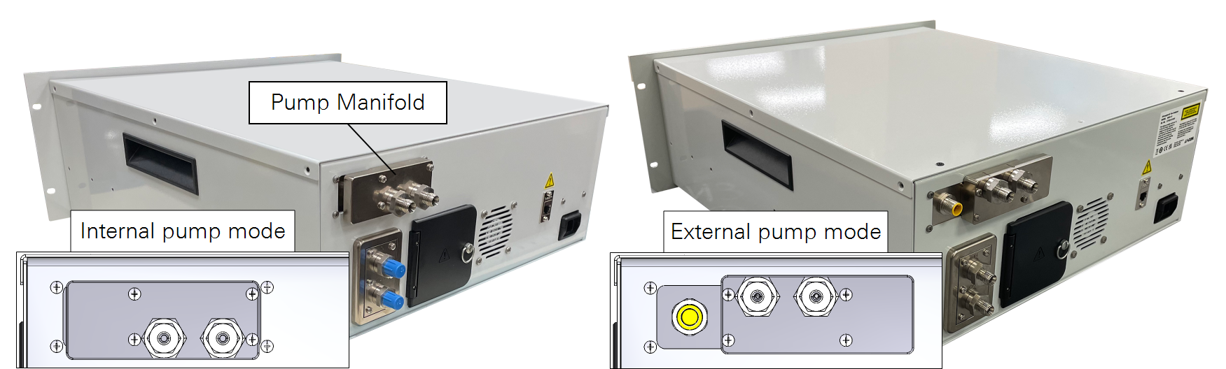
An external pump can be used instead of the built-in pump. When configured for the external pump, the power connector for the external pump is exposed. The two compression fittings for the external pump are now connected to the flow path. When the external pump power cable is installed, and analyzer will use the external pump; the internal pump is disabled and flow to the internal pump is blocked.
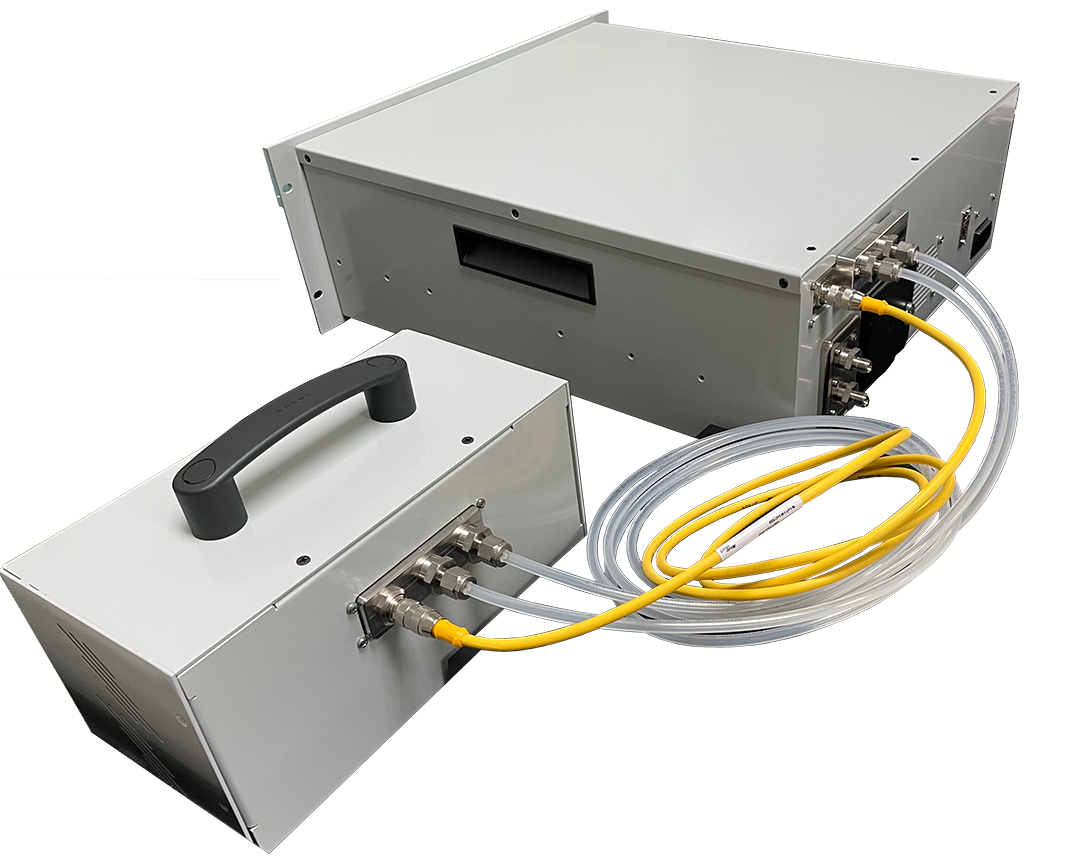
The external pump is powered by the gas analyzer. It has air inlet and outlet ports and a power cable connector, all of which are to be connected to the gas analyzer.

To connect the external pump, power off the analyzer and follow these steps:
-
Flip the pump manifold.
Remove the four screws that secure the manifold. Be sure the four O-rings stay in place, and then rotate the manifold 180° and reinstall it using the four screws. This exposes the connector and modifies the flow routing, directing flow through the external pump instead of the internal pump.
-
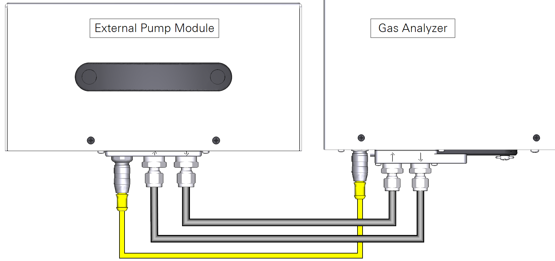
Connect the tubes and cable between the external pump and gas analyzer.
Tubes will connect the outlet from the gas analyzer to the inlet on the pump and the outlet from the pump to the inlet of the analyzer. Each end of the tube includes a compression fitting with bushing and ferrule and an insert to make the tube firm. Tight each nut and compression fitting to finger tight and then ¼ turn more.
To stop using the external pump, power off the analyzer, disconnect the power cable and return the pump manifold to the original position.
Power options
Mains power
The power connector accepts a C13 connector from the power cable. It is compatible with 100 to 240 VAC power sources, both 50 and 60 Hz. The analyzer can also be powered by removable rechargeable batteries. We recommend leaving at least one battery in the instrument when on to ensure proper shut down if main power is lost unexpectedly.
Rechargeable batteries
Two batteries can be installed behind the battery cover. When not using an AC power supply, a single battery is required to power the instrument. The instrument supports hot-swapping, meaning that you can install a charged battery and remove a partially depleted one and measurements will not be disrupted — as long as the instrument is powered by a charged battery or an AC power supply.
The batteries are not user serviceable. If a battery exceeds a temperature or load threshold, a non-resettable fuse will open, rendering the battery non-functional. If the batteries become excessively discharged in storage, the charger will supply a 3-minute wake-up charge in an attempt to activate the electronics. If this does not work, the battery should be replaced.
Charging batteries in the instrument
Batteries in the instrument are charged any time the instrument is powered by the universal power adapter. The charge status is given in the web interface, the instrument display, and on the battery.
Charging batteries with an external charger
The optional single-bay charger (part number 590-11830; Inspired Energy CH7000A) can charge one battery at a time. To use the charger, plug it into a wall socket and place a battery in the dock. The charger is compatible with 100 to 240 VAC; 50 to 60 Hz. A blinking LED indicates charging; solid green indicates a full charge.
Note: An optional automobile adapter kit is available to charge the battery from an automobile. Leave the automobile running when charging the battery to prevent excessive discharge of the automobile battery.
Warning: Charge batteries only with a SMBUS compliant level 2 or 3 charger. Do not heat above 80 °C. Do not open battery, dispose of in fire, or short circuit—may ignite, explode, leak, or get hot, causing personal injury. Replace battery with same part number only. Use of another battery may present a risk of fire or explosion. Keep away from children.