Printable PDF: Collecting Samples from the Smart Chamber
(8100_AppNote_Collecting_Trace_Gas_Samples_08937)
Download this content as a pdf that can be saved to your computer or printed.
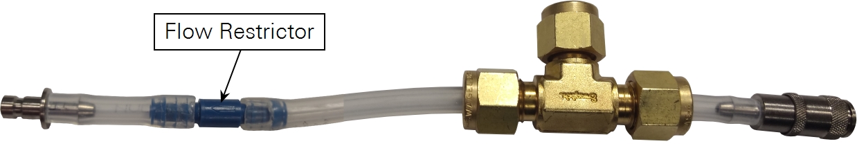
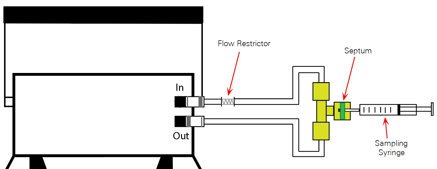
Assembling the kit for use with the Smart Chamber is the same as the LI-8100A instructions presented above, except that it uses the flow restrictor and requires you to cut an additional length of tubing. The flow restrictor is placed in the length of tubing extending from the compression fitting arm with the Smart Chamber air in connector (the smaller of the two quick-connect fittings). Assemble the kit according to the following instructions.
- Remove the brass nuts from the compression fitting.
- Locate the tubing with quick-connect fittings, two sets of ferrules, the flow restrictor, and cut an additional short (5-7 cm) length of tubing.
- Install a brass nut and one set of ferrules on the Smart Chamber air out connector segment (the larger of the two), and install the other nut and ferrules on one end of the additional length of tubing you cut. Note the orientation of the ferrules. The smaller, beveled piece must be installed first, facing the correct direction. When installed, the end of the tube should extend approximately 3 mm (1/8") beyond the ferrules.
- Insert the septum into the remaining nut. The septum has a self-sealing plastic coating on one side (identified by the glossy coating). For optimum sealing, install the septum with the glossy side facing the T-fitting.
- Assemble the T-fitting. Tighten the nuts, but do not over-tighten them, as this could create leaks around the septum and ferrules.
- Insert the flow restrictor into the bare tubing extending from the T-fitting.
- Attach the remaining length of tubing with air-in connector to the other end of the flow restrictor. Insert the barbs of the restrictor as deep as possible into the tubing.
- Attach the connectors to the Smart Chamber.