The CNF4 Heating and Ventilation Unit (part number 7900-145) is used to prevent condensation or frost buildup on the Kipp & Zonen CNR4 pyrgeometer windows and pyranometer domes. Condensation on the pyrgeometer windows will absorb far-infrared radiation and lead to measurement errors. These can be avoided by using the CNF4. See the manufacturer’s documentation for more information. Here we describe how to use the CNF4 in LI-COR biomet data acquisition systems. Read the manufacturer's instructions before using the CNF4.
Note: Due to heat dissipation from the CNF4, measurements of sensor temperature may be less accurate. However, the improvements in accuracy that result from heating will be larger than errors that result from heating.
Components
The CNF4 kit includes the heater/ventilator, three pan-head machine screws with washers, four flat-head screws, the protective shroud, and the CNF4 power cable. Cables are available in 10, 25, and 50 meter lengths.
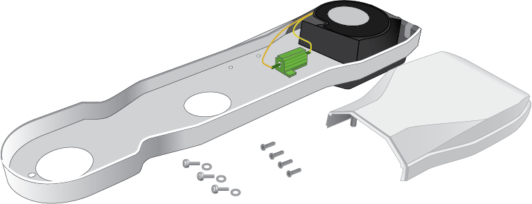
The CNF4 kit includes two relays to control the power supply (part number 290-14669) and a pack of wire leads. It includes four 11-cm 18-gauge red wires, two 30-cm 20-gauge blue wires, and one 11-cm 18-gauge black wire (not used). The relays and wire leads are required for Sensor Package 4 only.
Assembling the CNF4
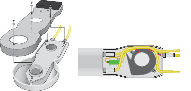
After attaching the temperature and sensor cables to the radiometer, attach the heater/ventilator to the CNR4 body using the three machine screws. Route the cables around the fan in the ventilator. Attach the protective shroud with the remaining four screws. Connect the ventilator power cable to the unit.
Installing the CNF4 control components
Different sensor packages have different wiring.
For Sensor the Premium Package and Package 2
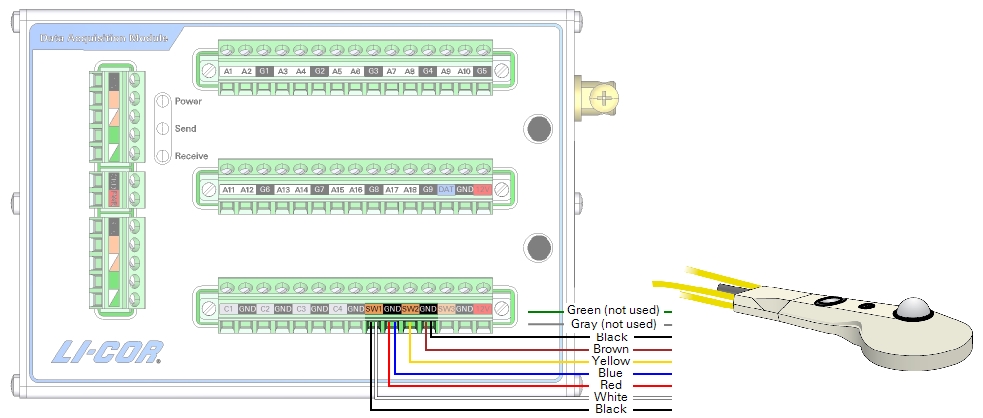
If you have two DAqMs, the CNF4 wires connect to the DAqM. The CNF4 is controlled by the DAqM's switched power supplies. The green and gray wires for the tachometer are not used.
| CNF4 Wire | Color | Connection |
|---|---|---|
| Ventilator (+) | Yellow | SW2 |
| Ventilator (-) | Brown | GND (SW2) |
| Tacho (+) | Green | Not used |
| Tacho (-) | Gray | Not used |
| Heater (+) | Black | SW1 |
| Heater (+) | White | SW1 |
| Heater (-) | Red | GND (SW1) |
| Heater (-) | Blue | GND (SW1) |
| Shield (black) | Black | GND (SW2) |
For Package 4 and custom packages
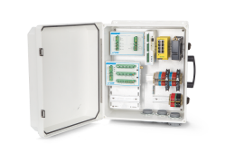
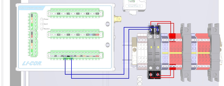
For Sensor Package 4, you'll need to install two relays and wire leads, which are required to actuate the relays and provide the timer-controlled power to the CNF4. The CNF4 wires connect to the relays and DIN terminals. The green and gray wires for the tachometer are not used.
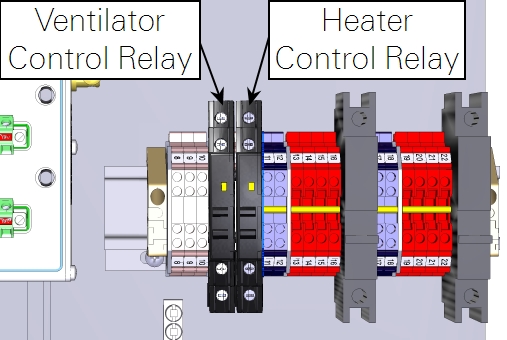
| Description | Color | Terminals Connected |
|---|---|---|
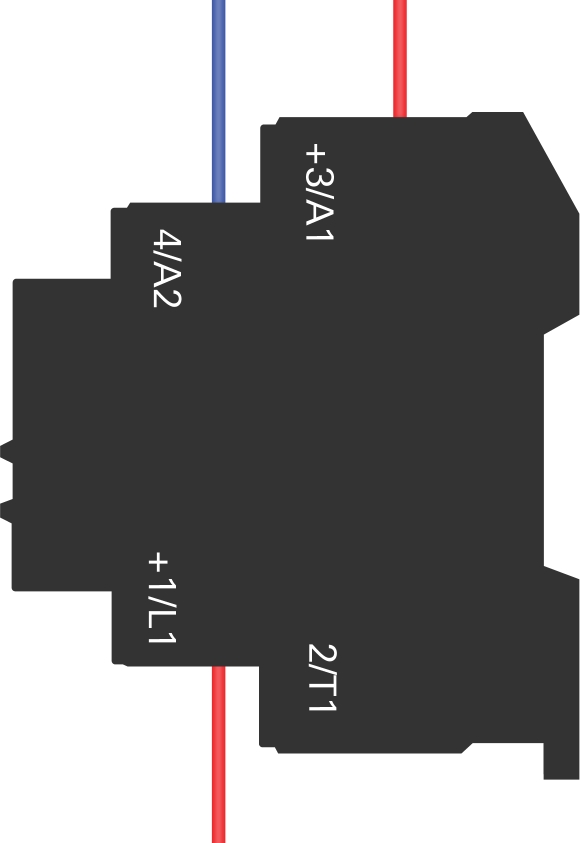
| Ventilator Relay Control | Blue | C4 to Left Relay 4/A2 |
| Ventilator Relay Power | Red | 13 to Left Relay +3/A1 |
| Ventilator Power | Red | 13 to Left Relay +1/L1 |
| Heater Relay Control | Blue | C3 to Right Relay 4/A2 |
| Heater Relay Power | Red | 14 to Right Relay +3/A1 |
| Heater Power | Red | 14 to Right Relay +1/L1 |
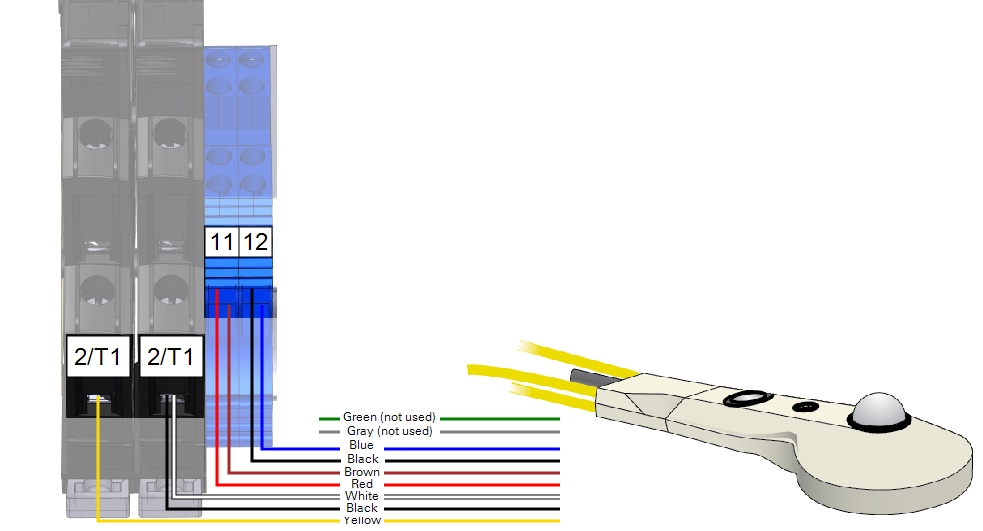
| CNF4 Wire | Color | Connection |
|---|---|---|
| Ventilator (+) | Yellow | Left Relay 2/T1 |
| Ventilator (-) | Brown | Blue DIN Terminal 11 |
| Tacho (+) | Green | Not used |
| Tacho (-) | Gray | Not used |
| Heater (+) | Black | Right Relay 2/T1 |
| Heater (+) | White | Right Relay 2/T1 |
| Heater (-) | Red | Blue DIN Terminal 11 |
| Heater (-) | Blue | Blue DIN Terminal 12 |
| Shield (black) | Black | Blue DIN Terminal 12 |
Configuring the timer controls
The required blocks are already included in programs that support the CNF4. The heater and ventilator are controlled by separate relays (and separate blocks) so they can be configured independently. Typically the heater should be on 1 hour before sunset to 1 hour after sunrise. Read the manufacturer's recommendations for more information.
In the Blueprint Utility, configure the timing parameters. Expand the Kipp & Zonen CNF4 block and set the Turn On time and duration for both the heater and the ventilation unit.