Installing sensors in the field
Field installation
This section describes field installation at the site. You can complete some parts of this procedure in a lab for initial verification.
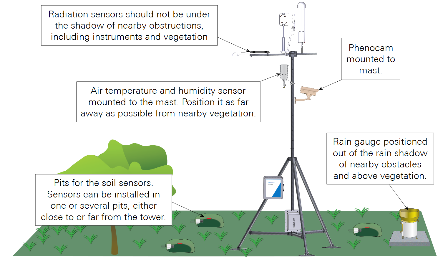
When planning the field installation, determine the best position for the sensors based upon your site conditions and your sampling objectives. The placement of sensors will affect the quality of data provided. Avoid shading light sensors. Measurements of soil and air properties should be within the eddy covariance fetch (the geographical area that is contributing to fluxes).
LI-190R and LI-200R radiation sensors
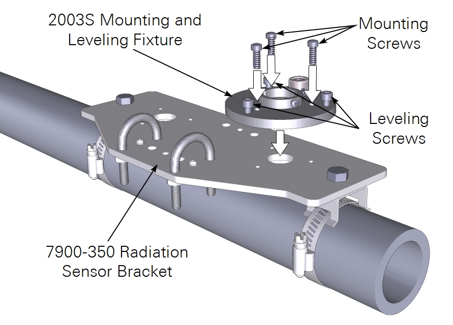
Install radiation sensors on the tower or tripod. Position them so that they will never be under the shadow of instruments or nearby landscape elements, and to minimize the amount of light that is reflected onto the sensors. It should be at least 1.5 meters above the nearby canopy.
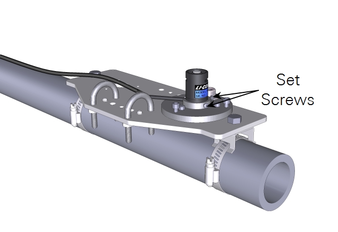
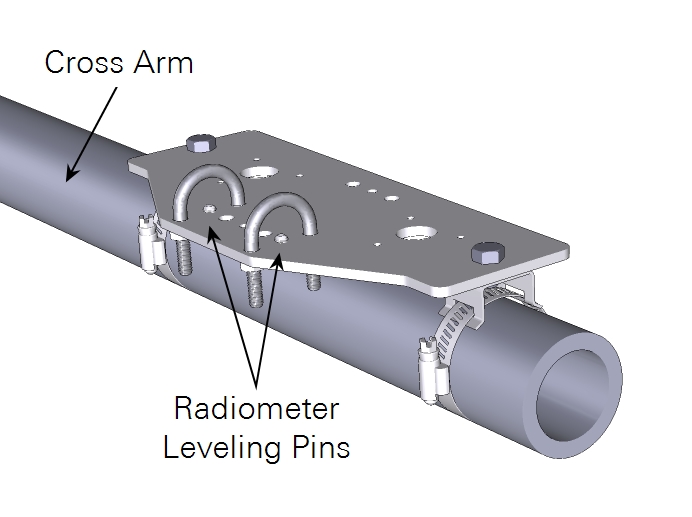
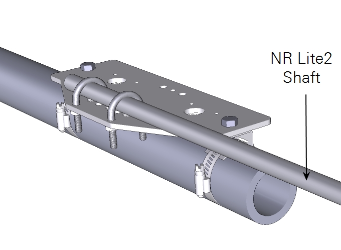
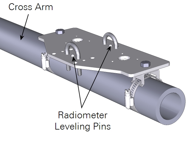
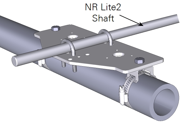
NR Lite2 net radiometer
Mount the NR Lite2 either parallel or perpendicular to the cross-arm in accordance with the instructions from the manufacturer. Orient the net radiometer boom toward the equator to ensure that it is not covered by a shadow of other things on the tower.
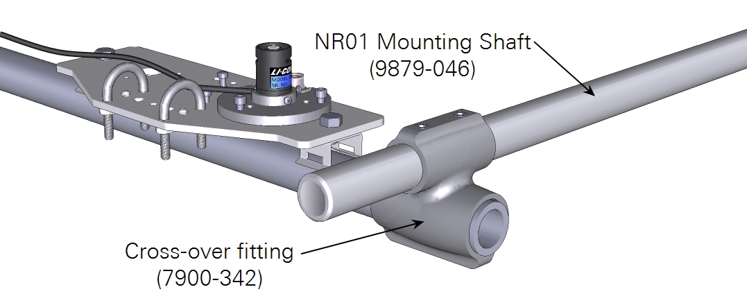
NR01 net radiometer
Mount the NR01 perpendicular to the cross-arm using a cross-over fitting in accordance with the instructions from the manufacturer. Orient the net radiometer boom toward the equator to ensure that it is not covered by a shadow of other things on the tower.
CNF4 radiometer heater and ventilation unit (for the CNR4 net radiometer)
Begin by attaching the temperature and sensor cables to the radiometer. Then attach the heater/ventilator to the CNR4 body using the three machine screws.
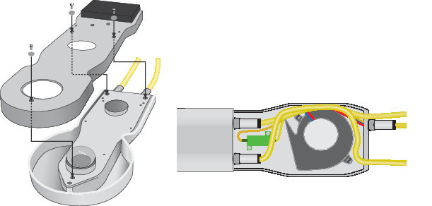
Route the cables around the fan in the ventilator. Attach the protective shroud with the remaining four screws. Connect the ventilator power cable to the unit.
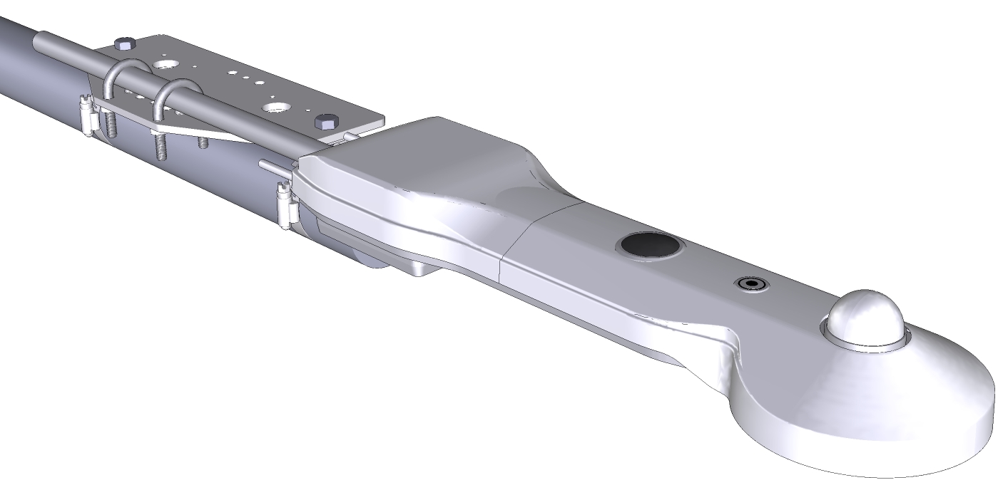
CNR4 net radiometer
Install the net radiometer so its view is unobstructed by adjacent structures, trees, and the meteorological station. Select a location that is away from heat sources. Orient the sensor with the sensing element pointing toward the equator to minimize shading from surrounding elements. Mount the sensor at least 1.5 m above the plant canopy.
Mount the CNR4 either parallel or perpendicular to the cross-arm in accordance with the instructions from the manufacturer.
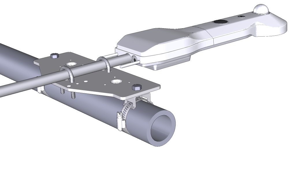
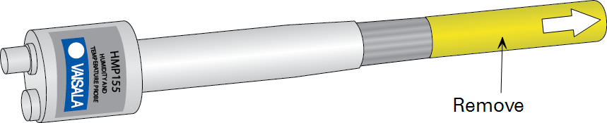
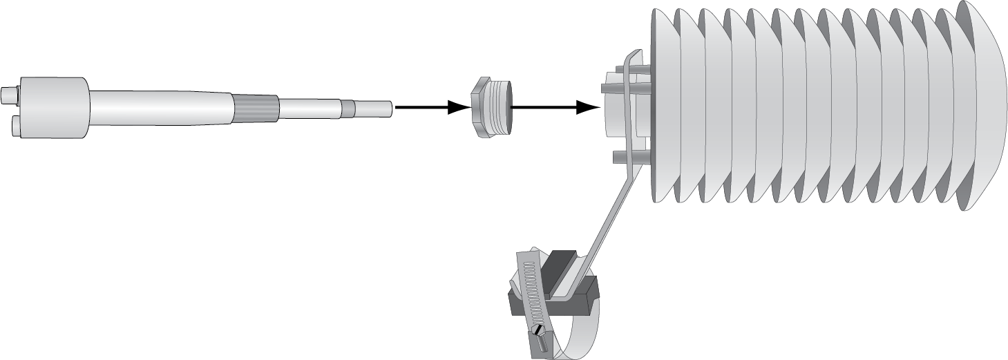
HMP155 air temperature and humidity probe
Place the HMP155 over an open, level area that is free of obstructions and at least 30 m from paved areas. Position the probe as far above vegetation as possible. Install the HMP155 at a minimum distance from nearby obstructions of at least four times the height of the obstruction.
Remove the protective cover and install the HMP155 in the radiation shield.
Position the sensor close to the sonic anemometer but far enough away that it won't obstruct airflow. Install it over an open, level area that is free of obstructions and at least 30 m from paved areas. Position the probe as far above vegetation as possible. Maintain a minimum distance from nearby obstructions of at least four times the height of the obstruction. If you will use the temperature measurement for eddy covariance data processing, position the sensor close to the sonic anemometer but far enough away that it won't obstruct airflow.
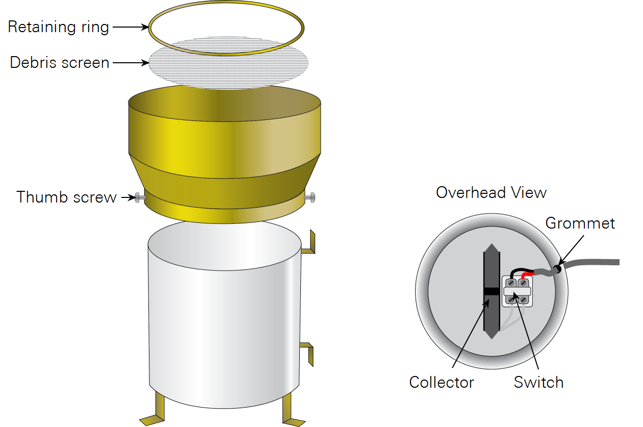
TR-525M rain gauge
The rain gauge is shipped partially assembled. To connect the cable, route it through the grommet in the side of the rain gauge, remove the black rubber cover from the cable connector, and connect the cable wires to the internal magnetic switch. Polarity doesn't matter in this case. Reattach the rubber cover.
Important: Be sure that the collector is not held in the center position by magnetic attraction. It must be tipped to one side or the other. If it is tied down, remove the string or rubber band.
Insert the screen into the funnel and secure it by pressing in the retaining ring. Secure the funnel to the body of the gauge by tightening the two thumb screws. Select a level location that is representative of the surrounding area. The funnel should be >30 cm above the plant canopy. The minimum distance from nearby obstructions is at least 2 times the height of the obstruction.
Select a level location that is representative of the surrounding area. The funnel should be >30 cm above the plant canopy. The minimum distance from nearby obstructions is at least 2 times the height of the obstruction.
Make sure the funnel is level and the body is plumb. Be sure the tipping bucket can move freely from side to side and that it is not stuck in the center position. If using a mast mount, be sure the mast is secure, stable, and plumb.
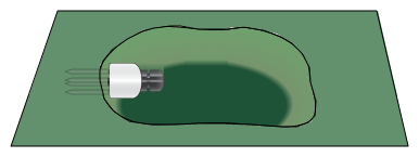
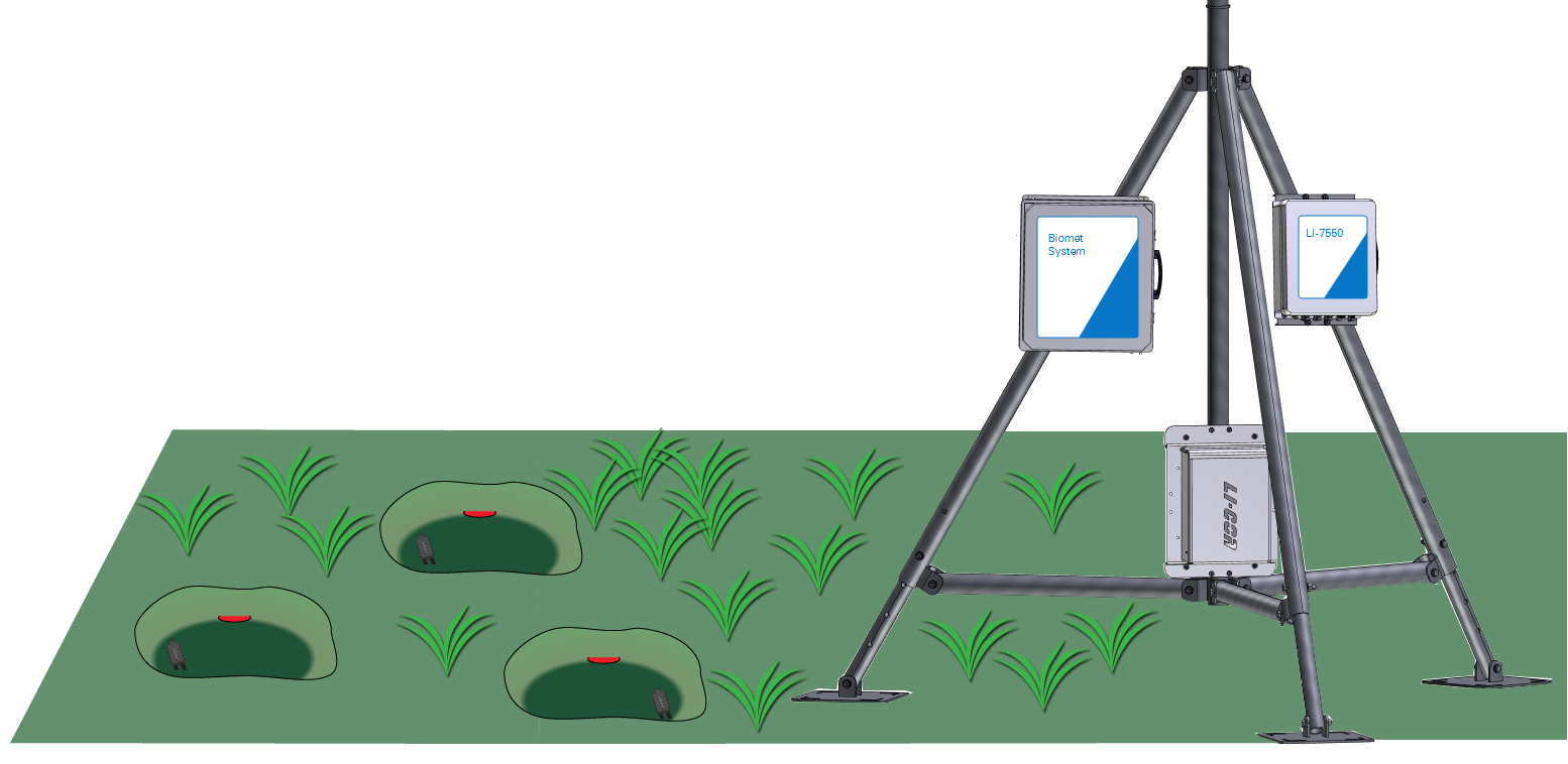
HFP01 soil heat flux plates and HFP01SC self-calibrating soil heat flux plates
In a typical installation, three or more heat flux plates are needed in order to ensure good representation of the site.
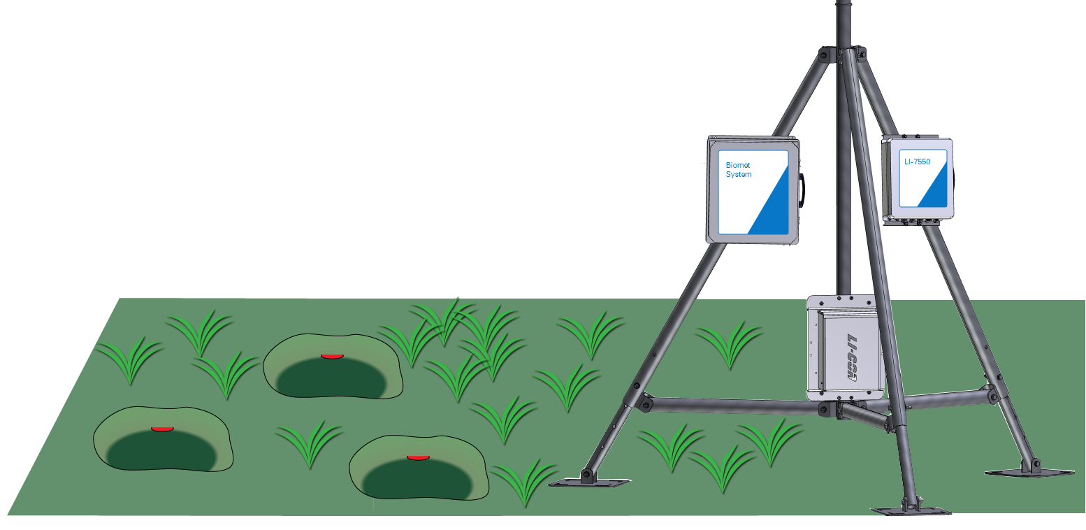
Place each heat flux plate in a shallow pit in soil that is representative of the site. More sensors may be needed if the soil is highly variable. Heat flux plates and soil moisture sensors and temperature sensors can be placed in the same excavation. Excavate a small hole with a smooth, undisturbed side. Keep the excavated soil as an intact block if possible. Make a horizontal slit in the smooth side of the excavation 5 cm below the soil surface.
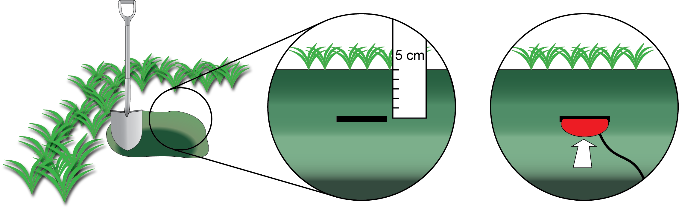
With the red side facing up toward the sky, gently insert the heat flux plate in the slit until it is completely covered by soil. Be sure the plate is in full contact with the soil and that there are no air pockets around it. Bury a length of the sensor leads to prevent thermal conduction through the wires.
Stevens HydraProbes
Place the probes in undisturbed soil that is representative of the site. Probes can be inserted directly into the soil surface or inserted into the soil in a pit.
Install the probes at a depth of 5 cm below the soil surface. Press the probe into the soil until the base of the tines is flush with the soil. Be especially careful to avoid creating air pockets when inserting the probe. Air pockets around the tines will reduce the accuracy of measurements.
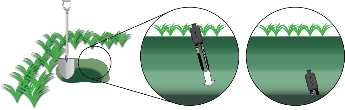
EC-5 soil moisture probes
Place the probes in undisturbed soil that is representative of the site. Dig a hole to the desired depth. Orient the flat side of the sensor perpendicular to the soil surface to minimize the effects of water. Push the prongs into undisturbed soil at the bottom or side of the hole. Be sure there are no air gaps and that the sensor is in complete contact with soil. Be sure the prongs are covered completely up to the over-molding.
7900-180 soil temperature probes
Place the soil temperature sensors in shallow pits near the soil heat flux plates and soil moisture sensors, in minimally disturbed soil that is representative of the site. Bury the sensors between 2 and 6 cm from the soil surface. Be sure each sensor is completely covered with soil and that there are no air pockets in contact with the sensor. Bury a short length of cable to prevent thermal conduction through the wires.
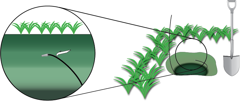
Backfill the holes to match the bulk density of the soil.
Stardot PhenoCam
Direct the camera to the north (in the northern hemisphere) to avoid lens flare and shadowing. Mount the camera at a height of 5 to 10 meters above the canopy. The camera angle should be less than horizontal to obtain the ideal balance of sky and canopy. The image should capture about 20% sky and 80% canopy. Be sure to include the horizon in the image. Mount the camera securely to prevent movement. See https://phenocam.nau.edu/webcam/ for details about using a PhenoCam.
The camera enclosure can be mounted to vertical post or horizontal mast with diameters from 2.5 to 6 cm (1 to 2.375 inches).
Mounting the camera
Below we offer some recommendations for the camera position. These guidelines are adapted from the PhenoCam network. See https://phenocam.nau.edu/webcam/ for details.
- Direct the camera to the north (in the northern hemisphere) to avoid lens flare and shadowing.
- Mount the camera at a height of 5 to 10 meters above the canopy.
- The camera angle should be less than horizontal to obtain the ideal balance of sky and canopy. The image should capture about 20% sky and 80% canopy. Be sure to include the horizon in the image.
- Mount the camera securely to prevent movement.
To install the camera:
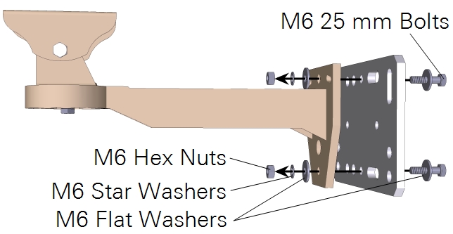
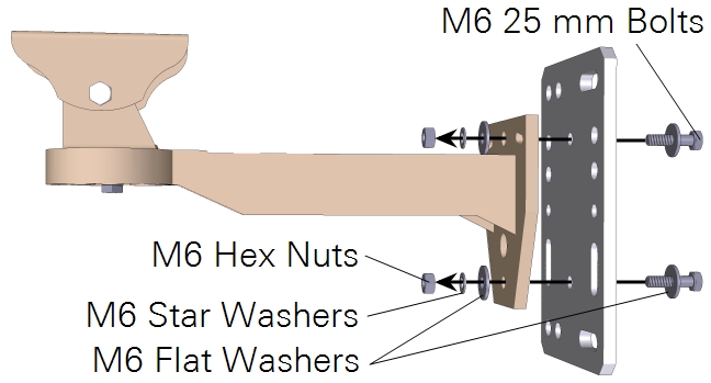
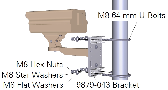
- Connect the StarDot PhenoCam Bracket to the mounting plate.
- The orientation of the plate will depend on whether you are connecting it to a vertical mast or horizontal cross arm.
| For mounting to a horizontal cross-arm: | For mounting to a vertical mast: |
|
|
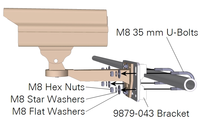
- Attach the camera enclosure to the mounting arm.
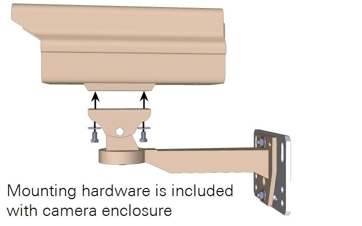
| For mounting to a horizontal cross-arm: | For mounting to a vertical mast: |
|
|
- Set the camera in the enclosure close to the window.
- Remove the gland plug from the camera enclosure and route the power/data cable through the opening.
- Connect the power/data cable to the camera, and to the power supply and network switch.
- Close the enclosure.
- Cover cable opening in the camera enclosure with putty to prevent insects from colonizing the enclosure.
Note: Not all of the mounting hardware will be used.
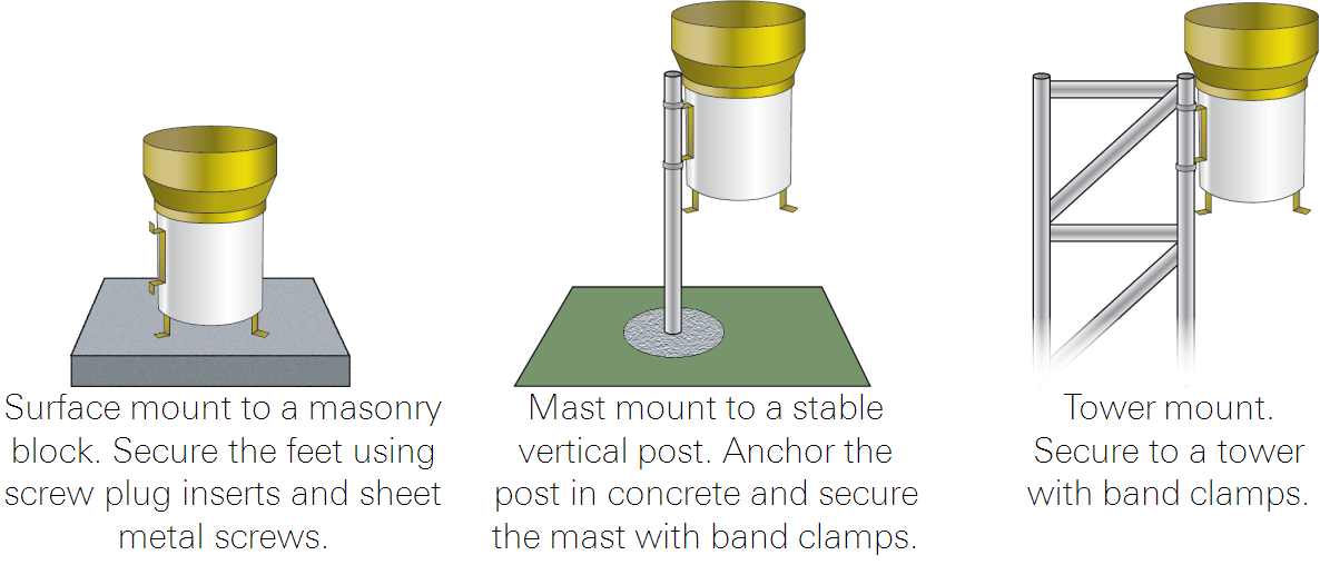
Mounting the enclosure
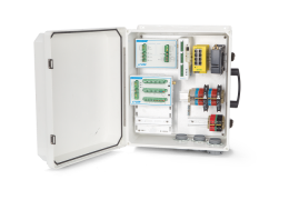
The enclosure includes mounting hardware that can be used to attach it to a tripod mast or leg. For the best protection against splashing rain, orient the enclosure vertically, with the openings facing the ground. Connect a ground wire between the system ground in the enclosure and a ground lug on the tripod or a dedicated ground rod.
Note: When mounting the enclosure to a tripod or tower, position it low on the structure to reduce turbulence that may affect eddy covariance flux measurements. A low mounting position also will reduce wind resistance, thereby reducing wind load on the structure.
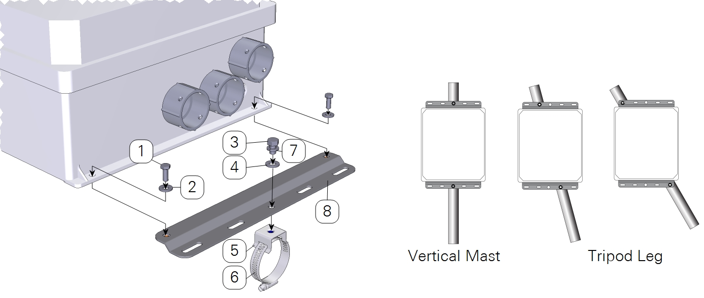
| Item | Qty. | Description | Part Number |
|---|---|---|---|
| 1 | 4 | M6 × 16 mm Hex Head Bolt | 150-12943 |
| 2 | 4 | Flat Washer 1/4 × 5/8” | 167-02054 |
| 3 | 2 | 5/16-24 × 1/2” Hex Head Bolt | included w/ item #5 |
| 4 | 2 | 5/16” Flat Washer | included w/ item #5 |
| 5 | 2 | Single Bolt Flared Leg Mounting Bracket | 235-13234 |
| 6 | 2 | Band Clamp, 9/16” | 300-13293 |
| 7 | 2 | Split Washer 5/16” | 167-05635 |
| 8 | 2 | Mounting Plate | 9879-044 |
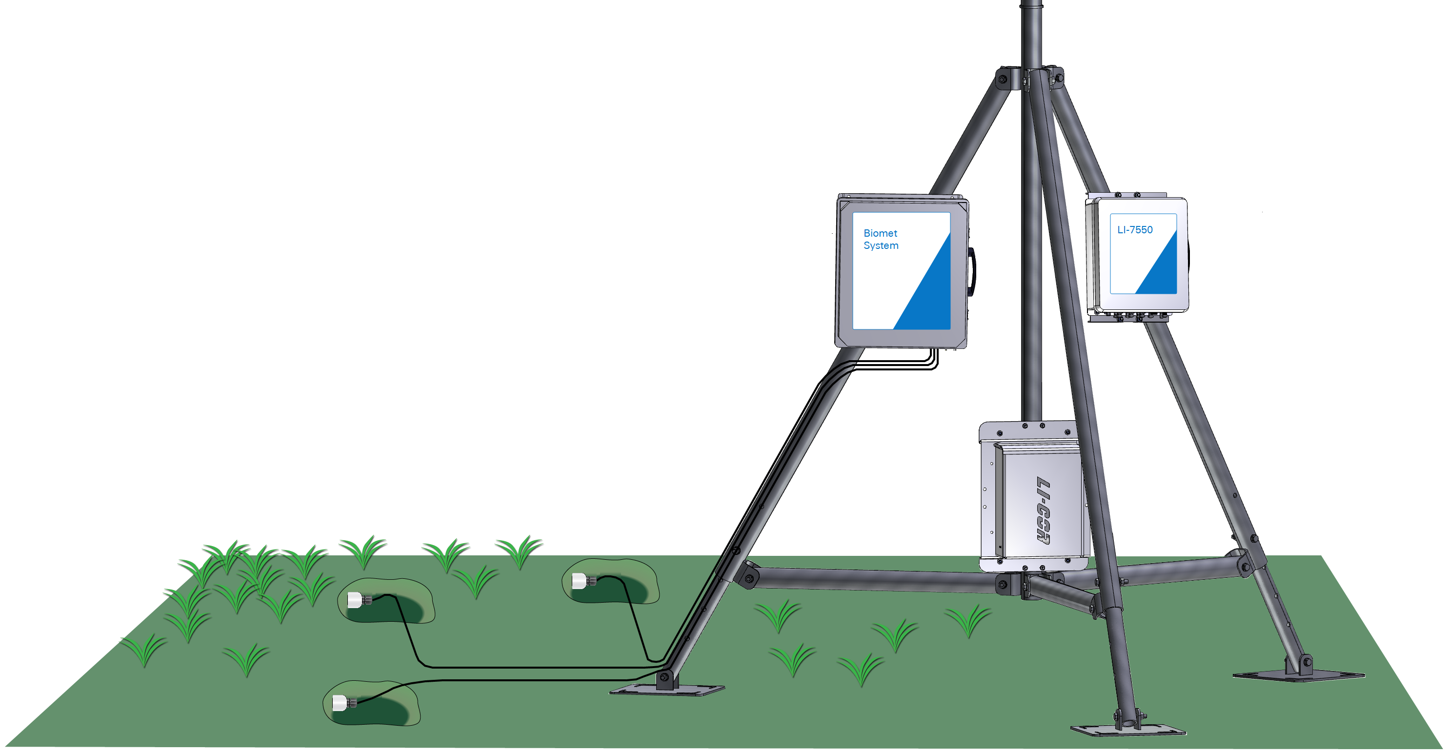
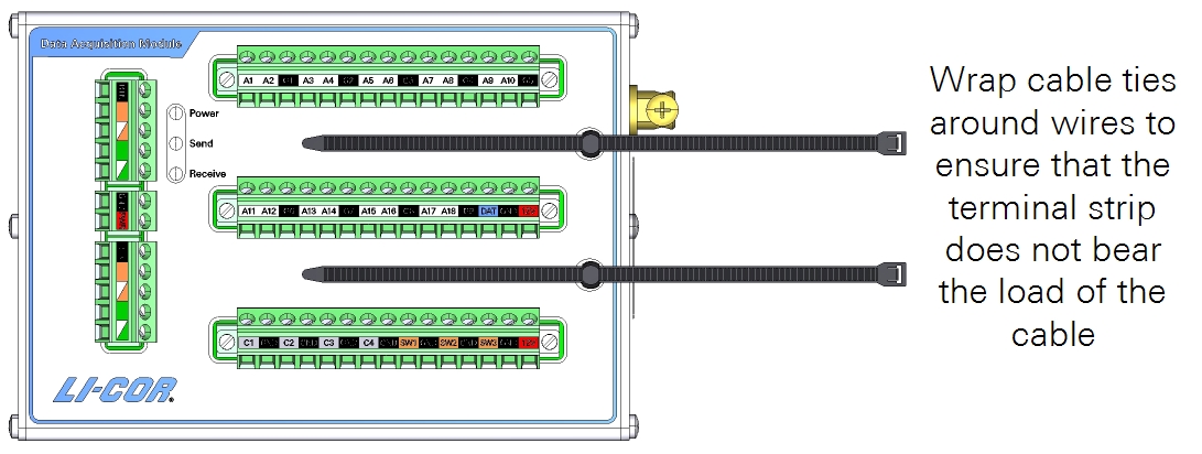
Securing cables
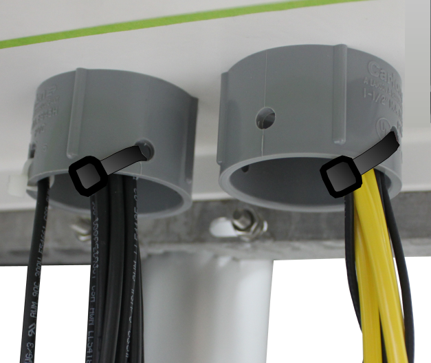
Each DAqM has anchors for cable ties. After you have installed sensor wires, wrap the cables with cable ties and secure them to the anchors to ensure that the terminal strips do not bear the load of the cables.
For cables that exit the enclosure through the bottom openings, use cable ties to secure the cables to the strain relief couplings on the enclosure. Cover empty holes with the red enclosure plugs (in place upon shipment, part number 620-12831). Stuff a piece of metallic wool into holes that are used for cables.