Logging for EddyPro
Field Setup for Logging Data in .ghg Files
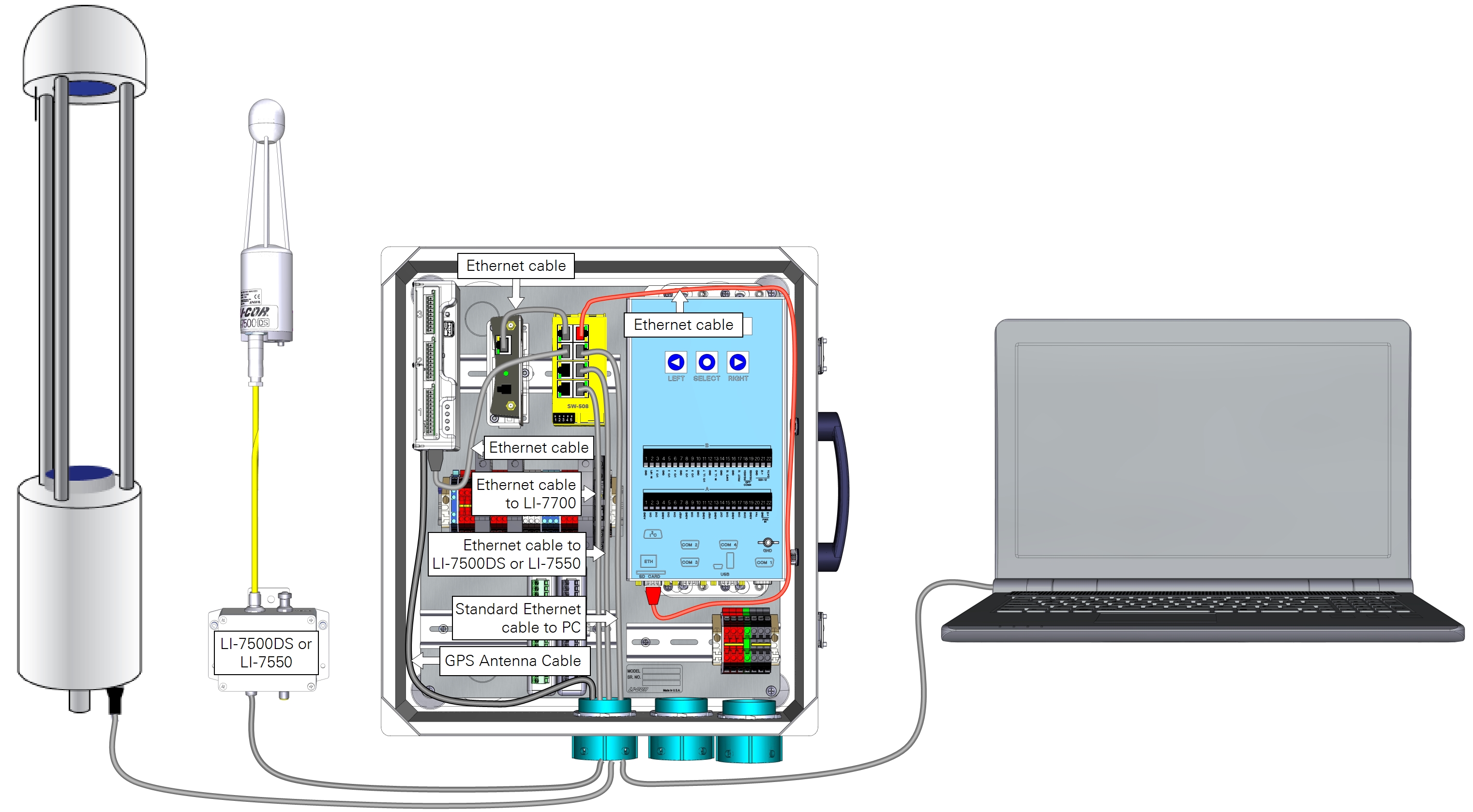
Under this configuration, biomet data are included in compressed .ghg files for processing in EddyPro or by the SmartFlux System. It includes a Biomet Station and LI-7500DS or LI-7550 (LI-7700 optional) that is not connected to network infrastructure with a DHCP server. The PC is optional—used only to configure the instruments. The cellular gateway and antenna (shown in Figure 3‑1) are optional, but present an ideal way to connect to the system from the Internet. This is the recommended configuration.
- Install the Data Cables.
- Prior to connecting the PC to the system, disable wireless internet access on the computer, disconnect any networked Ethernet connections, and set the PC network to "dynamic."
- Connect to the Datalogger.
- This connection should be via RS-232 serial (see Configuring the Biomet System). Under the Setup tab, click LAN Settings, and then click Settings. Dismiss any software prompts (do not use the wizard).
- Configure the Network Properties.
 For the Field Setup the system is not connected to a network that includes a DHCP server. The IP Address: 169.254.100.100 and Subnet Mask: 255.255.0.0 are the default network settings assigned to the datalogger prior to delivery. If you are using a wireless communication system, set the Network Properties as required for the wireless network.
- Restart the datalogger to apply the settings.
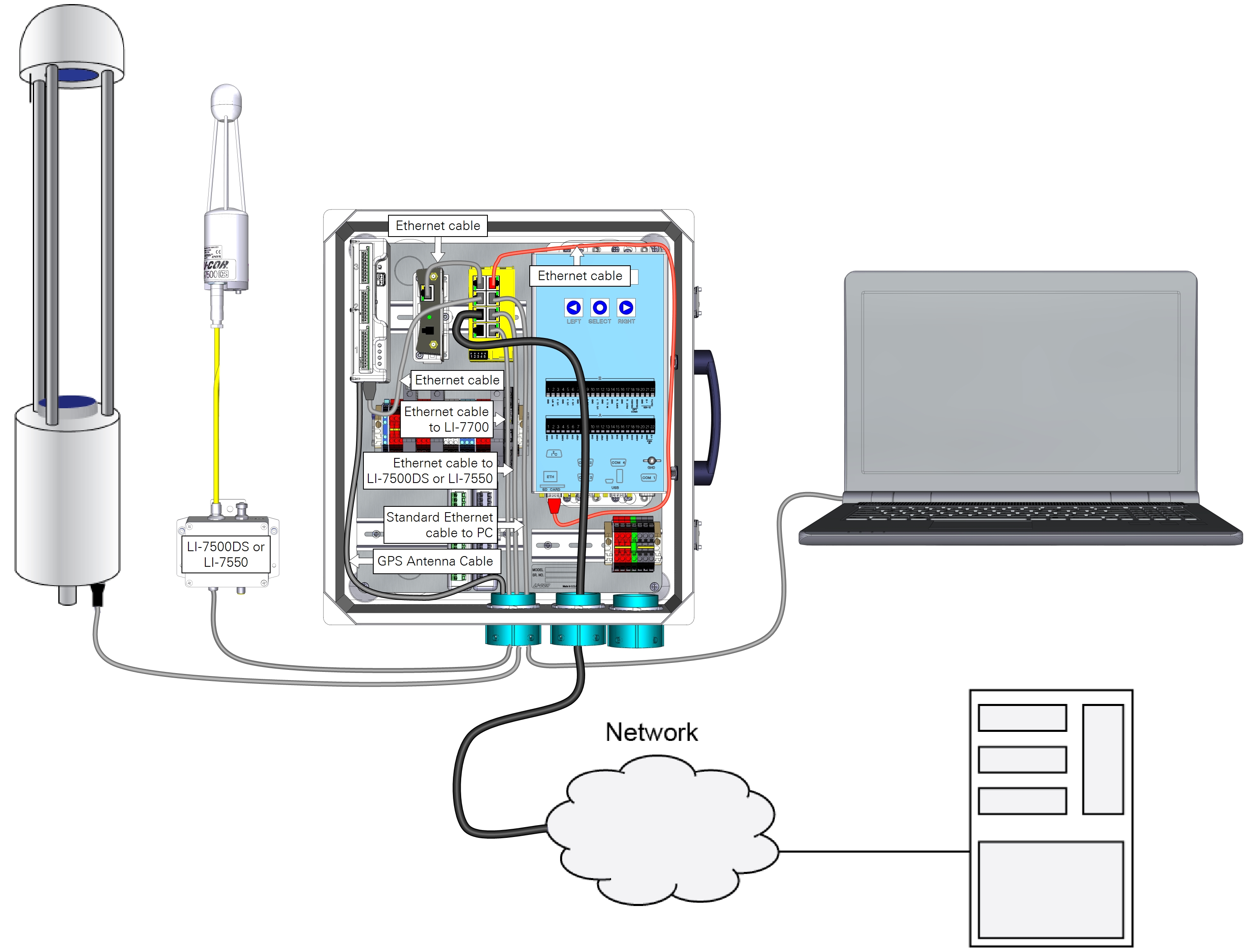
Office Setup for Logging Data in GHG Files
This setup is similar to the previous configuration, the difference being that the eddy covariance system is connected to a computer network with a DHCP server.
- Install the Data Cables.
- In this configuration, set the both the PC and datalogger network setting to Obtain IP address via DHCP.
- Connect to the Datalogger.
- First, connect to the datalogger via RS-232 serial (see Configuring the Biomet System). Under the Setup tab, click LAN Settings, and then click Settings. Dismiss any software prompts (do not use the wizard).
- Configure the Network Properties.
- For the Office Setup. The Obtain an IP address via DHCP setting is used if you are connecting your eddy covariance system to an existing network.

- Restart the datalogger to apply the settings.
Stand-Alone Setup
Notes on Networking
According to the IPv4 requirements link-local addresses are in a block of IP addresses ranging from 169.254.1.0 to 169.254.254.255. By default, the datalogger has a static link-local address of 169.254.100.100.
Why a static IP address? If the datalogger is configured to acquire an IP address automatically (Obtain an IP address via DHCP), when you connect the datalogger to a network where a DHCP server is running, the server will assign it an IP address for that network. Later, when you connect the datalogger to the LI-7550 (at the research site, for example), the LI-7550 will not be able to communicate with the datalogger because it has no way to determine the datalogger IP address. This is because the LI-7550 assigns itself a link-local IP address and connects with other devices with link-local addresses, but not with devices that have addresses that were assigned previously by a DHCP server. The static IP address reliably solves this problem.
Although we recommend using a static IP address—and the datalogger is indeed configured that way by default—you can still set the LAN Settings to Obtain an IP address via DHCP. Under this configuration the datalogger will be assigned an IP address the first time it is connected to the network. To assure that the LI-7550 will establish and maintain communication with the datalogger, both must be connected to a network switch on a network with a DHCP server. The DHCP server will assign IP addresses to the LI-7550 and datalogger (and LI-7700).
Validate Eddy Covariance Data Integration
Important: For more information, refer to the LI-7500A/RS or LI-7200/RS instructions and EddyPro documentation (www.licor.com/eddypro)
The steps below show how to verify that the biomet data will be logged with the .ghg data files on the LI-7550.
- Connect the Biomet Station to the LI-7550
- Be sure the Biomet Station is powered up, configured, and connected to the eddy covariance system. Launch the LI-7200/RS/LI-7500A/RS software (version 6 or above) and connect with the gas analyzer.
- Click the Site Setup (
 ) button and select the Biomet tab.
 - Click on the settings button (
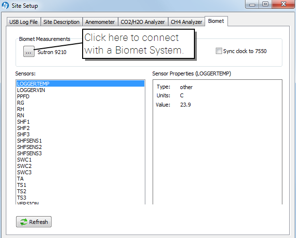
 ). Select your datalogger from the list and click Connect, and then click OK.
If the datalogger does not appear in the list, check the network settings of the Sutron 9210B and the LI-7550 (see Field Setup for Logging Data in .ghg Files).
The software will display a window with two columns. In the left column, you will see a list of the sensors. When you select a sensor in this column, the sensor type, units, and value will be displayed in the right column. If everything is displayed as expected, this indicates that the configuration is correct.
Retrieving Data
First, biomet data are bundled in .ghg files and saved on the USB drive. We recommend this setup because the data are all together in one file, and they can be easily summarized with EddyPro software and the SmartFlux System.
In the second scenario, data are logged to the internal memory or the expanded memory (SD card or USB drive) of the datalogger.
Note: Even if you bundled Biomet Data with .ghg files, a backup of the Biomet data will usually be stored in the datalogger, although it may be limited in size, depending upon the settings of the datalogger and available memory. The default memory size is 20MB, which will fill up after 1 month of logging 25 variables every minute.
Follow the steps below to retrieve your logged data from the datalogger.
- First, connect a computer to the datalogger using the RS-232 cable.
- See Configuring the Biomet System or use Ethernet for faster data transfer (See the 9210B User Manual for more information).
- After a successful connection, select the Log tab.

- Click the Export button.

- Select the Format and Download options. Set the Start Time and End Time if needed.

- Select a directory on your computer and save the files.

Warning: If you select a file name that already exists in the directory, the existing file will be overwritten without issuing a warning to you.
Data File Format
The data file is a comma delimited text file (or whichever format you selected) that can be opened in any text editor or spreadsheet program such as Microsoft® Excel.
The first row is the variable header, which includes the names of each variable. Its contents will vary, depending upon which sensors are in use at your site. All variable headers include the Date, Time, and Record ID, followed by labels for the sensors. The second row indicates the units of each variable.
Each program (e.g., Biomet_100) generates output files arranged in columns that include data from the sensors.
Variable Labels
If you used one of the preinstalled programs, variables are labeled in the data files according to the convention given below. If you used a custom program, variables are logged with the label you specified in the program.
| Variable | Label | Units |
|---|---|---|
| Date | Date | mm/dd/yyyy |
| Time | Time | HH:MM:SS |
| Record ID | RecID | RecID |
| Soil Water Content | SWC_1_1_1 | m^3/m^3 |
| Soil Temperature | Ts_1_1_1 | C |
| Photosynthetic Photon Flux Density | PPFD_1_1_1 | umol/m^2/s |
| Global Radiation | Rg_1_1_1 | W/m^2 |
| Air Temperature | Ta_1_1_1 | C |
| Relative Humidity | RH_1_1_1 | % |
| Precipitation (rain) | P_rain_1_1_1 | mm |
| Net Radiation | Rn_1_1_1 | W/m^2 |
| Shortwave Incoming Radiation | SWin_1_1_1 | W/m^2 |
| Shortwave Outgoing Radiation | SWout_1_1_1 | W/m^2 |
| Longwave Incoming Radiation | LWin_1_1_1 | W/m^2 |
| Longwave Outgoing Radiation | LWout_1_1_1 | W/m^2 |
| CNR4 Temperature | TCNR4_1_1_1 | C |
| Albedo | Alb_1_1_1 | none |
| Soil Heat Flux | SHF_1_1_1 | W/m^2 |
| Soil Heat Flux Sensitivity | SHFSens_1_1_1 | uV/W/m^2 |
| Soil Heat Flux Plate Heater | SHFHeater_1_1_1 | V |
| Datalogger Voltage In | LoggerVIn _1_1_1 | V |
| Datalogger Temperature | LoggerTemp_1_1_1 | C |
| Datalogger Power Source | LoggerPower_1_1_1 | none |
| Software Version | Version_1_1_1 | - |
Variables that occur more than once in the file are indicated with an incremental increase in the first digit, as: SWC_1_1_1, SWC_2_1_1,....
This naming and numbering convention is similar to that used by the GHG-Europe project. However, the policy specified in the GHG-Europe labeling system is not fully implemented here. In the GHG-Europe specification, the three indices have specific meanings and are designed to unequivocally identify data coming from a specific sensor. See VariableID.