1. Install the Datalogger Software on your PC
Download the software from www.sutron.com/downloads. Find the Xpert2/9210B Xterm software. Or, copy it from the Sutron Product CD.

If using the DC, click Autorun or open the CD directory and double-click Manuals&Utils. Click Software Utilities > Xpert-XLite Dataloggers. Click XTerm and your computer will prompt you to save the file. Save it and launch XTerm.
XTerm can run from any directory on the computer, including the desktop or a USB drive.
If the power supply is connected, switch the power breaker to the ON position. The datalogger will issue two series of chimes, separated by about 1 minute. The second series of chimes indicates that the device is ready to use.
Install the 1.8 m (72 in) male-to-female straight through RS-232 cable between the computer and Sutron COM1 port (a USB-to -serial adapter may be needed).
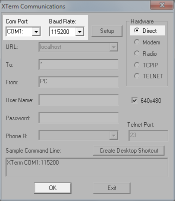
In XTerm, select the correct Com Port and Baud Rate (115200) and click OK.
Initial configuration is easiest through the RS-232 serial connection, rather than Ethernet.
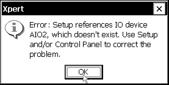
Note: Initially the datalogger will issue an error message indicating that the AIO modules have not yet been configured. Click OK to dismiss the error. It will be resolved in a subsequent step.
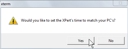
The datalogger clock can be synchronized to your computer's clock.
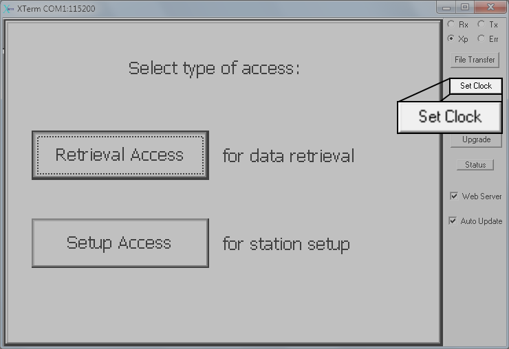
To set the time, click Set Clock. When prompted, click Yes to synchronize the clocks.
After connecting with the datalogger, click Setup Access. In the Main tab, set the Station Name. Station names can be up to 16 characters. Use uppercase characters only.

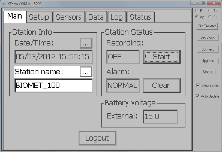
Important: Upon start-up, the datalogger will automatically load a setup file with the same name as the Station name. The station name MUST be the same as the program (setup file) name. For the preinstalled configurations, enter BIOMET_100 (BIOMET_101, BIOMET_102, etc.). If the names do not match, the datalogger will not load a setup file when it restarts, resulting in a failure to record data.
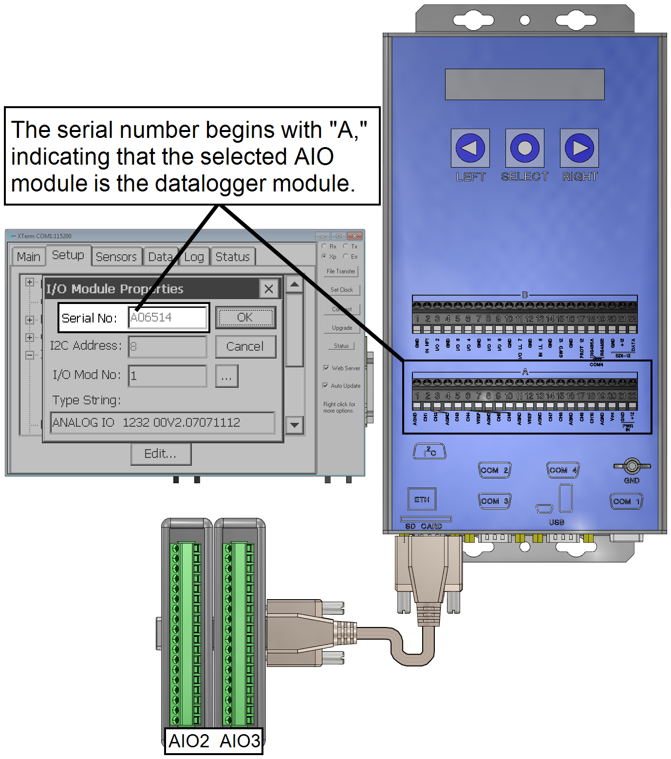
The Sutron datalogger can address up to 99 additional AIO modules. Each AIO module must be properly identified in the Sutron datalogger software. This is accomplished by associating each AIO module (identified by the serial number) with an AIO#, where # is the module.
Note: Serial numbers are printed on the AIO module. Each serial number that is printed on the AIO module has one extra digit that is not recognized by the Sutron software. Ignore the first value of the serial number.
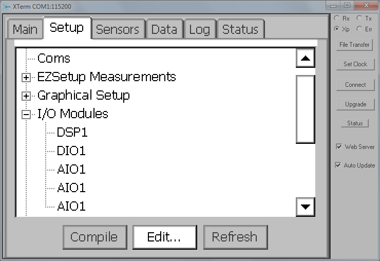
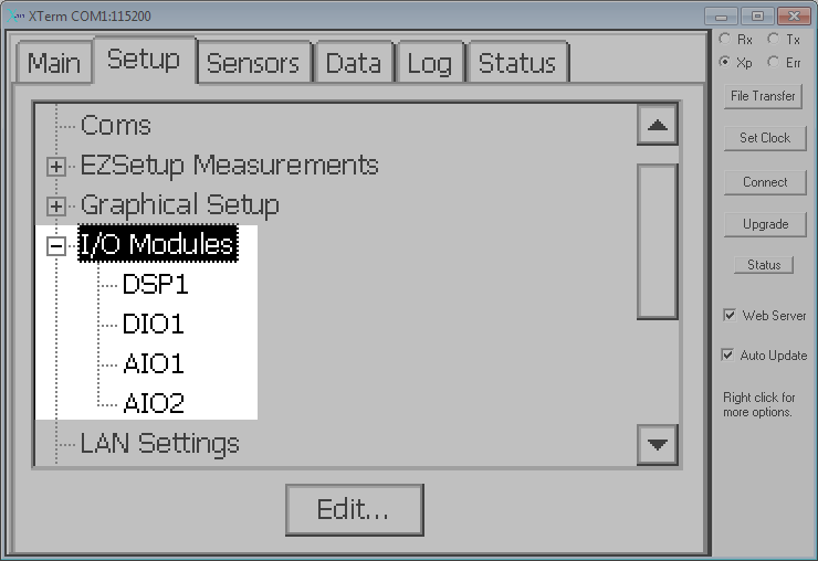
Under the Setup tab, click the [+] sign next to I/O Modules to expand the list.
Typically, you will notice several occurrences of "AIO1." Select the first one and click Edit.
Note: Analog modules are referred to as AIOx, whereas digital modules are DIOx, where x represents the module number.
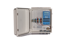
In the edit dialog, observe the field called Serial No. If the serial number of the module starts with the letter "A," that module is the terminal strip on the front of the datalogger (see Figure 1‑1). Click OK or Cancel. Select the second AIO module from the list and click Edit.
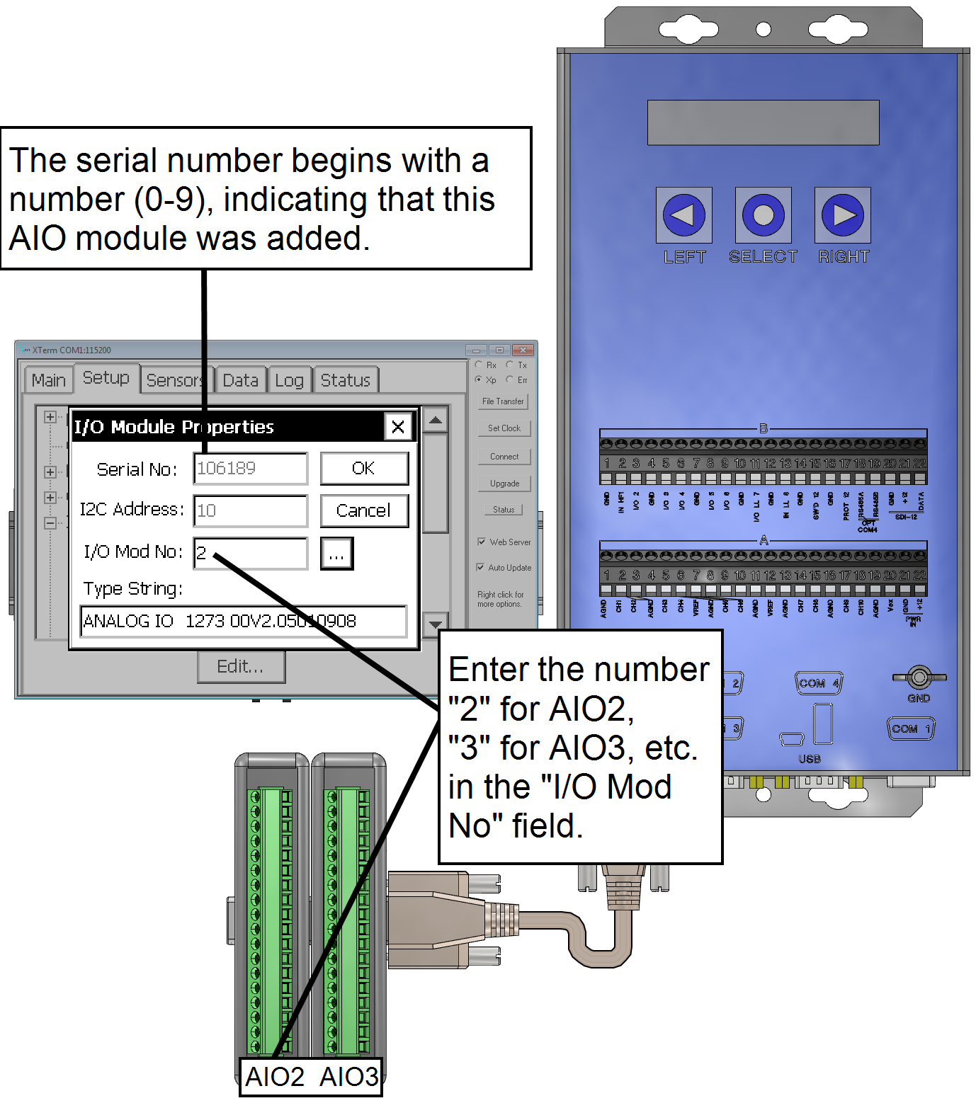
By contrast, if the serial number begins with a number, that module is one of the modules you've added to the system (see Figure 1‑2). Referring to the serial numbers recorded earlier (see Attach the AIO Module(s) to the AIO Plate), determine which serial number is associated with the AIO module located at the lower left in the enclosure.
Enter the # from the AIO# in the field called I/O Mod No so that the serial number you enter corresponds with the AIO#. Do this for each AIO module.
When properly configured, each AIO module will have a unique number, as shown Figure 1‑3.
Note: Preinstalled biomet programs require either one or two additional AIO modules. Additional modules can be added to expand the number of channels.
The header can include the Station name entered earlier, however, if you wish to process your data in EddyPro the header must be configured so the station name is not included in the logged file, but the data header and units header are included. This step shows how to configure the header.
Under the Setup tab select Log Files and then click Edit.
This will open the Log Files dialog:
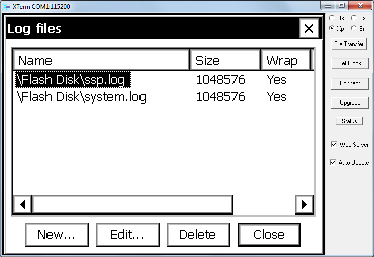
Select the ssp.log file and click Edit....
Note: If you added an SD Card or USB Drive, create a log file in it other than the ssp.log file shown in the example.
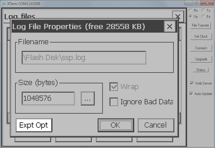
Click the Expt Opt button.
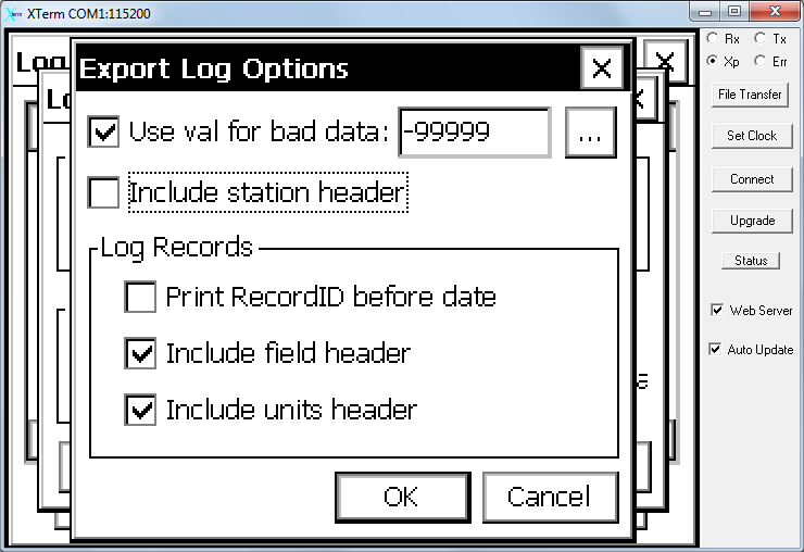
- Check the Use val for bad data: box and be sure the field reads ‑99999.
- Uncheck the Include station header box.
- Be sure Include field header and Include units header are checked.
This will ensure that the header includes variable identifiers and units, and that the biomet data can be interpreted by EddyPro.
Click OK on the open windows and click Yes when prompted to modify the log file. Close the Log file dialog.
8. Configure Datalogger Communications
The proper communications configuration will depend on how you intend to deploy the Biomet Station—whether it will stand alone, log data in a field setup (LI-7500DS or another CO2/H2O analyzer with the LI-7550), or log data in an office setup. Each of these scenarios is described in detail in Logging for EddyPro.