1. Install the Datalogger in the Enclosure.
Mount the datalogger in the enclosure (if you are installing the battery, see Overview of the 7900-127 Charge Controller). The datalogger mounting screws (part number 122-00012) are installed in the risers prior to delivery.
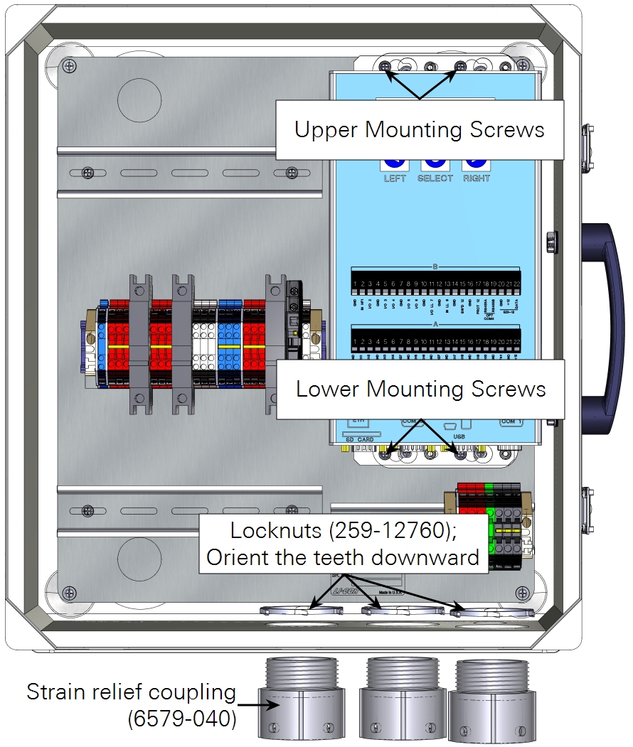
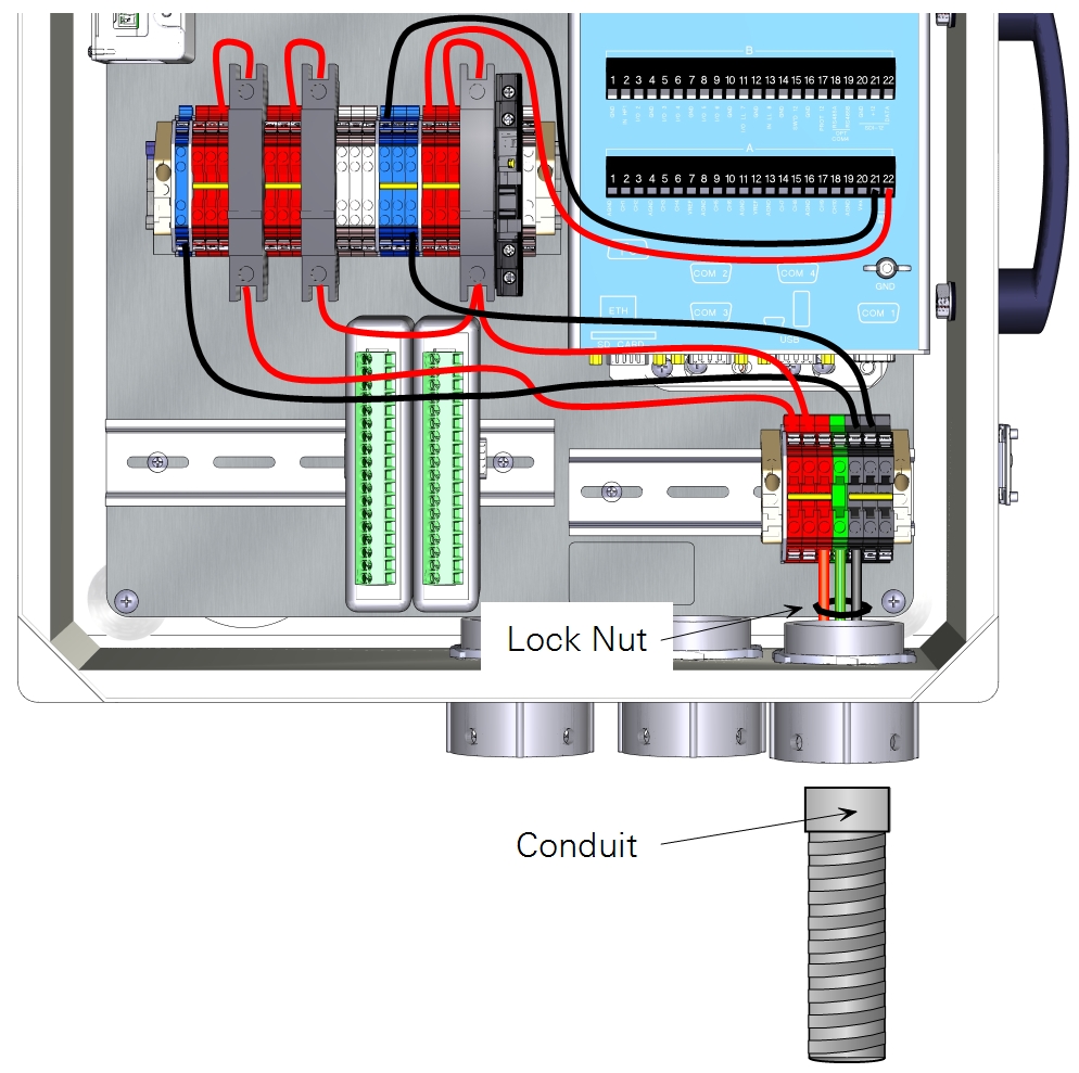
Install strain relief couplings (part number 6579-040) and lock-nuts (part number 259-12760) in the openings in the bottom of the enclosure. Orient the lock-nut teeth downward so it locks in place.
2. Attach the AIO Module(s) to the AIO Plate
Each AIO module (part number 7900-124) should be attached to the AIO plate using two screws (part number 122-00009). Up to two AIO modules can be mounted on a single plate. An optional 4-module plate is available (9979-006).
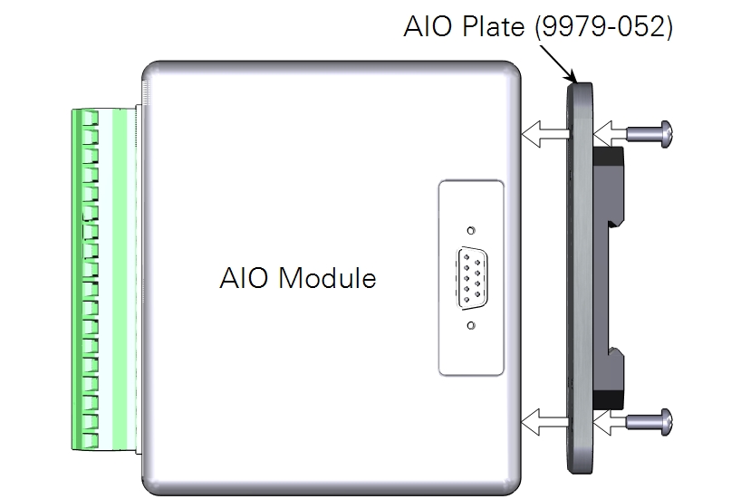
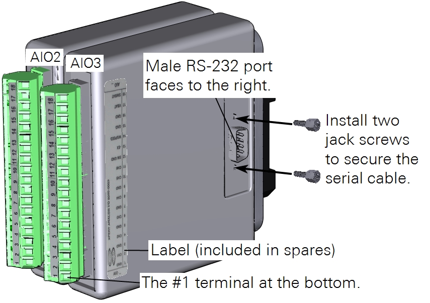
Install two jack screws in the right-most AIO module, in place of the screws.
Note: Record the serial number of each AIO module. The serial number is printed on the side of the module. This information is required for subsequent configuration.
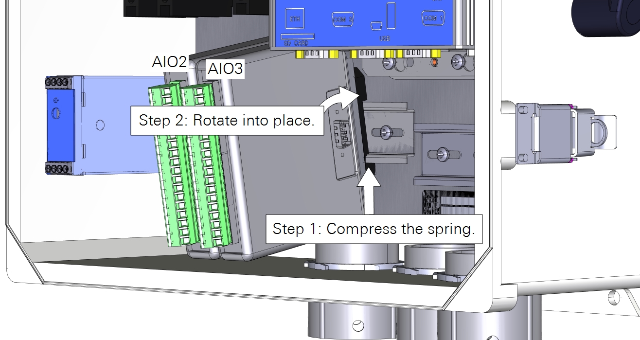
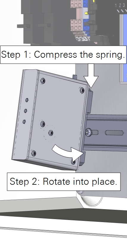
3. Install the AIO Plate in the Enclosure
The AIO mounting plate mounts to the lower left DIN rail in the enclosure. Locate the spring-loaded clasp on the mounting bracket. Position this clasp against the DIN rail (1), compress the spring, and then move the mounting bracket into place (2). The modules are numbered from left to right (AIO2, AIO3, etc.).
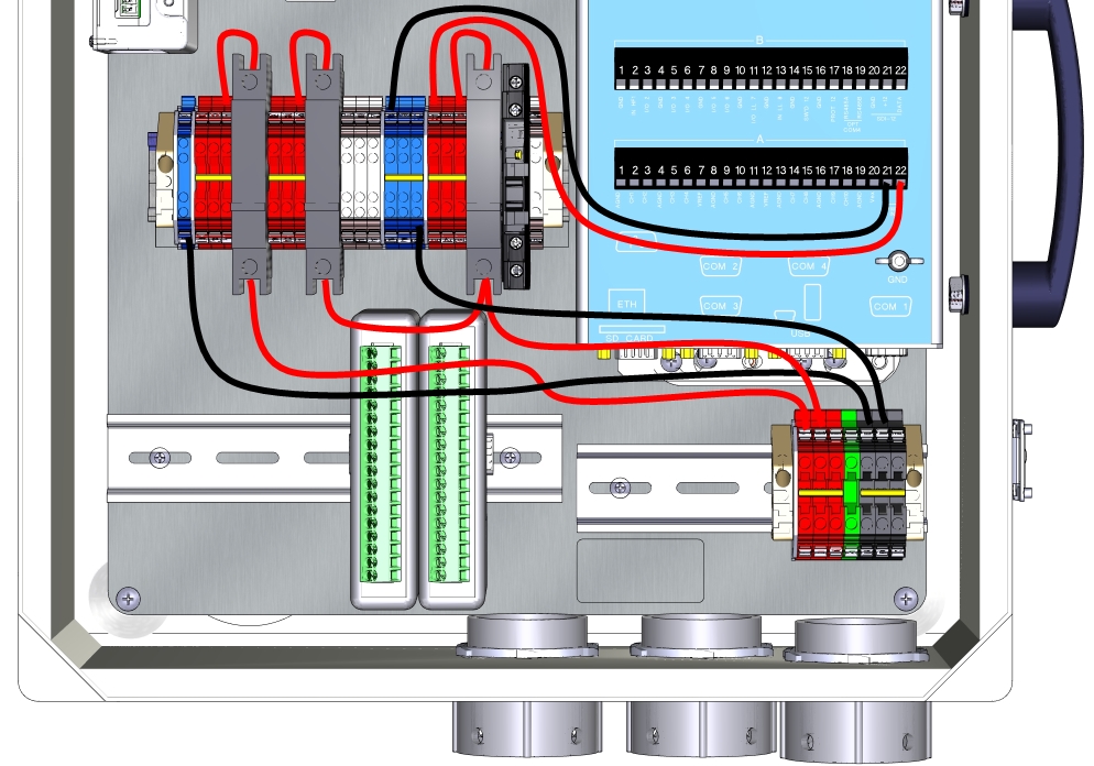
4. Install the power wires
Power wiring follows one of three scenarios. Select the one that applies to you and follow the directions.
Note: Terminal connections may vibrate closed during shipping. Loosen each terminal completely prior to inserting a wire lead.
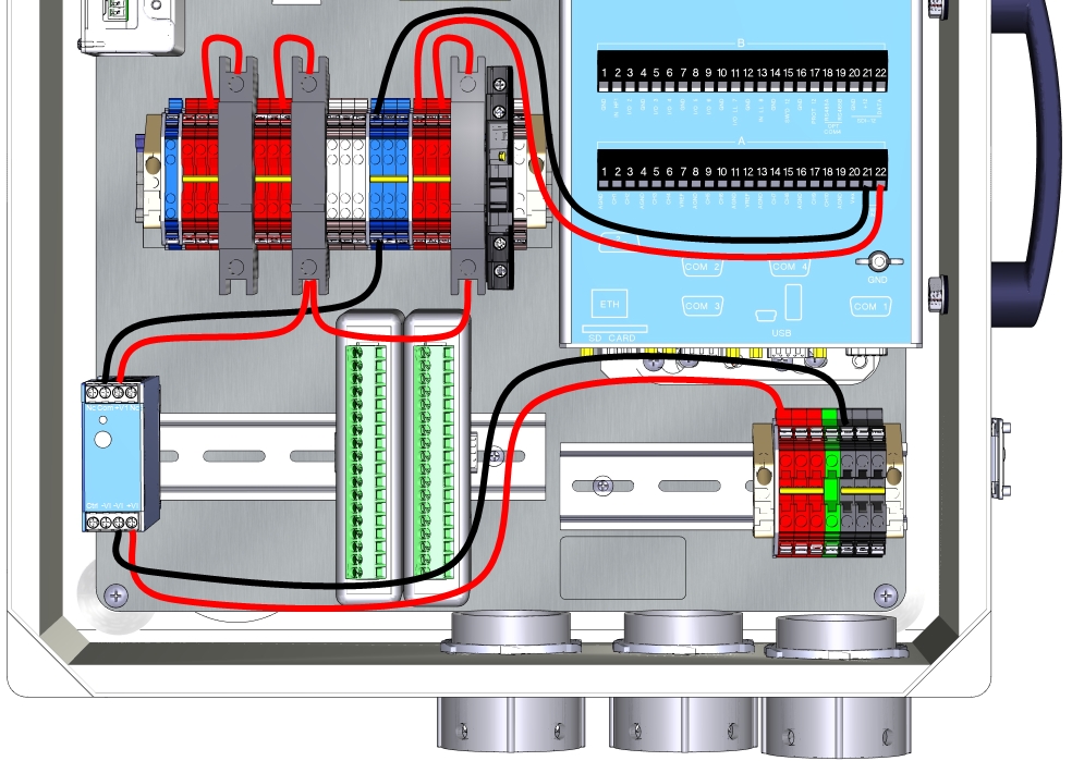
- If you are using a 12 VDC power supply:
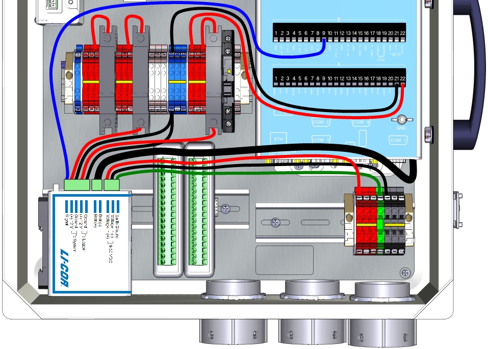
- If you are using a 24 VDC power supply with the TDK-Lambda DC-to-DC converter:
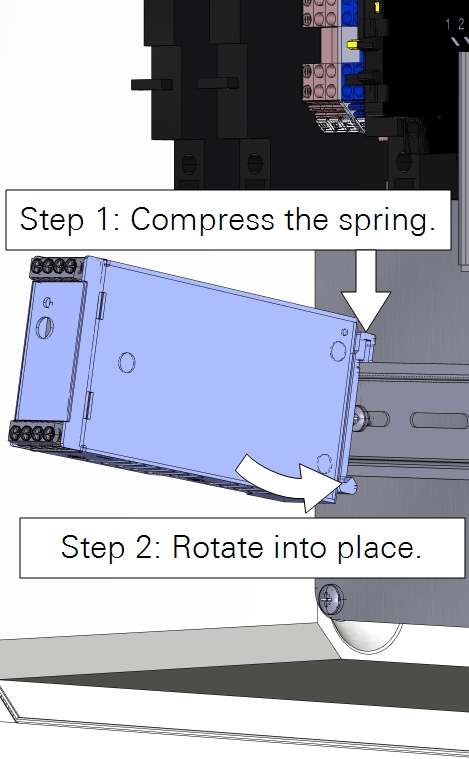
- For more details, see Overview of the TDK-Lambda DC-DC Converter.
- If you are using a 24 VDC power supply with the backup battery and 7900-127 charge controller:
For more details, see Overview of the 7900-127 Charge Controller.
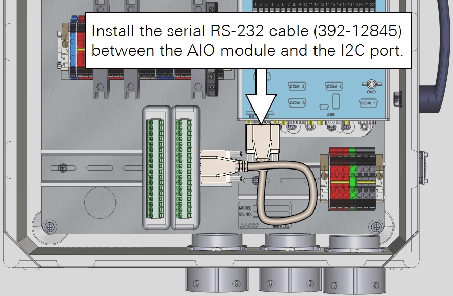
5. Install the Datalogger/AIO Data Cable
Locate the 30 cm (12 inch) RS-232 cable (part number 392-12845) in the Accessories Kit. Remove the bolts from the threaded connectors and install it between the male RS-232 port on the AIO module and the port labeled I2C on the datalogger. Secure the serial cable to the jack screws.
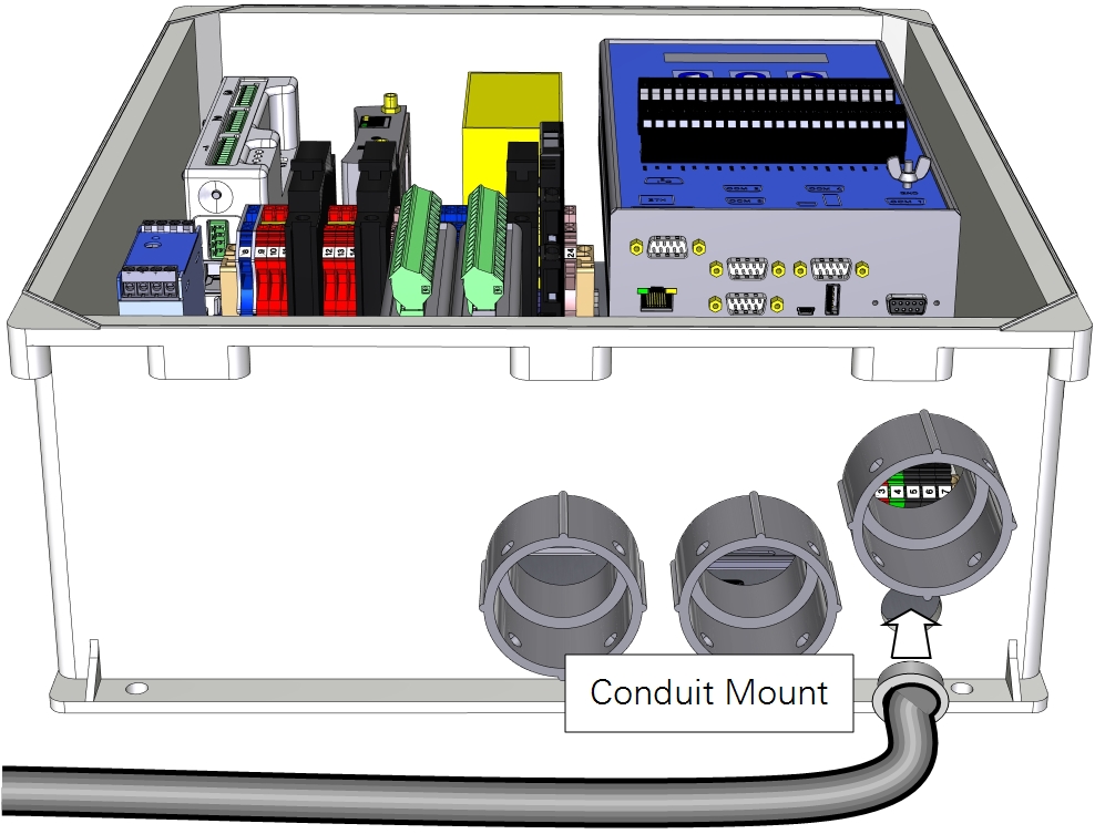
6. Connect the main power supply
The Biomet and Systems Enclosure has a power supply junction where you can connect conduit. Secure conduit (with the power cable) to the enclosure.
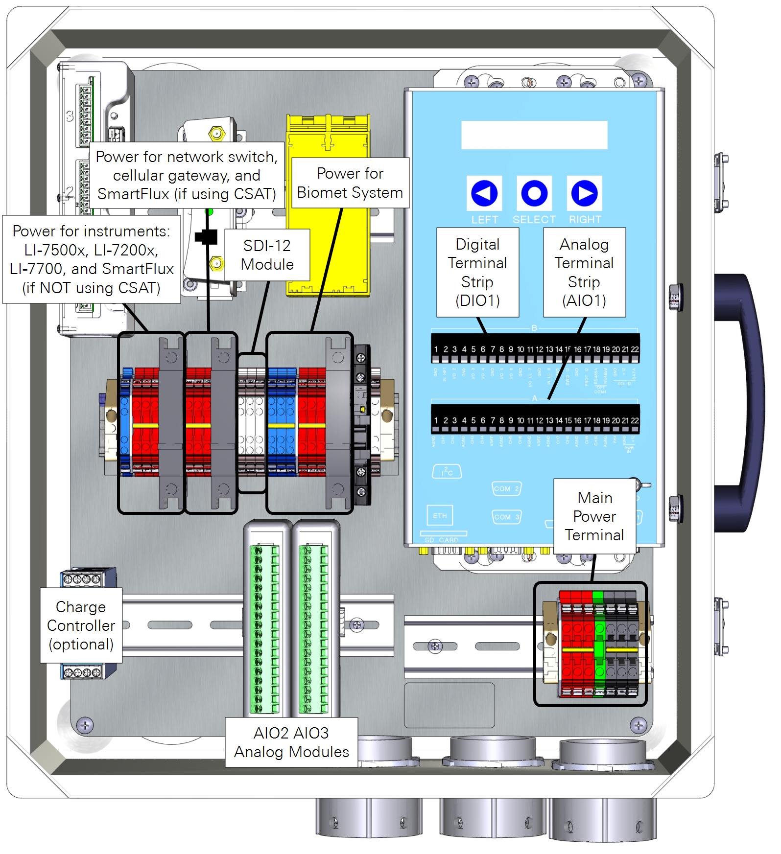
Components of the Assembled Biomet System
The components of an assembled Biomet system are labeled below: