Initial assembly
This section describes how to assemble and deploy the communication system. The following tools are required:
- Phillips and Standard slotted screwdrivers
- Bolt drivers or wrenches: 16 mm, 13 mm, and 8 mm (5/8", 1/8", and 5/16" approximate SAE equivalents)
- Post driver for antenna post
The hardware installation will take about 30 to 60 minutes. Software configuration will take about 30 minutes to 2 hours.
Note: We recommend that you fully assemble the system, configure your data plan, and test the system in your office or lab before deploying it in the field. Allow ample time to troubleshoot any issues and to verify that everything is working as expected to avoid having to make unplanned site visits.
Preparing the enclosure
Start by assembling the enclosure hardware.
Installing the system power supply cable
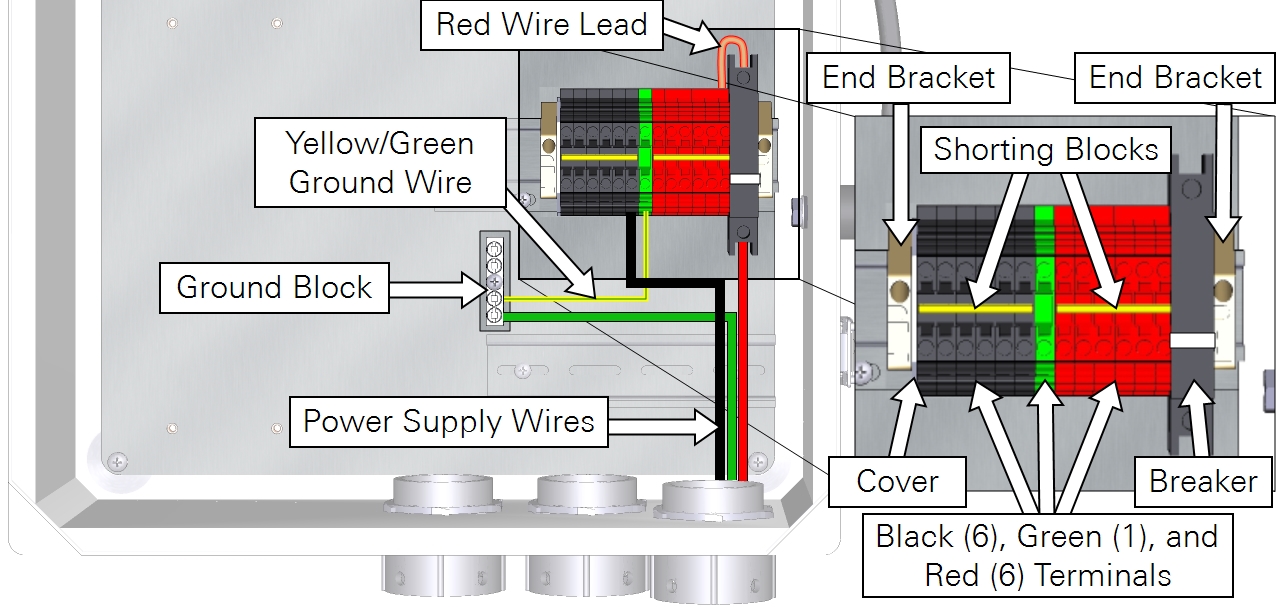
Connect the main power supply conduit to the small opening in the enclosure. Orient the lock-nut teeth so that they make contact with the enclosure surface. Connect the main power supply wires to terminals 3, 4 and 5.
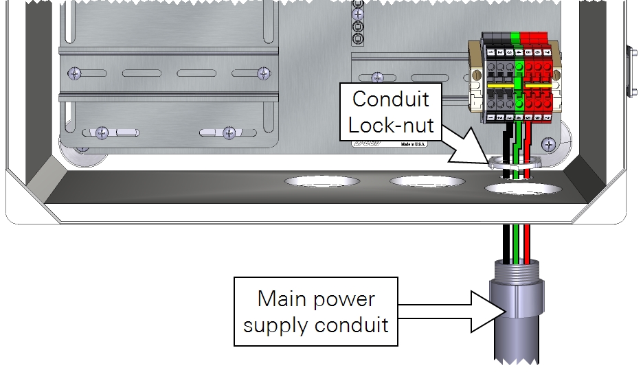
As a good practice, be sure that your power cable is not connected to a power source until the wiring is complete. Keep the breakers in the OFF position until you are ready to power up the system.
| From | Wire Color | To |
|---|---|---|
| Main power (-) | black | DIN Terminal 3 (bottom) |
| Earth ground | green | DIN Terminal 4 (bottom) |
| Main power (+) | red | DIN Terminal 5 (bottom) |
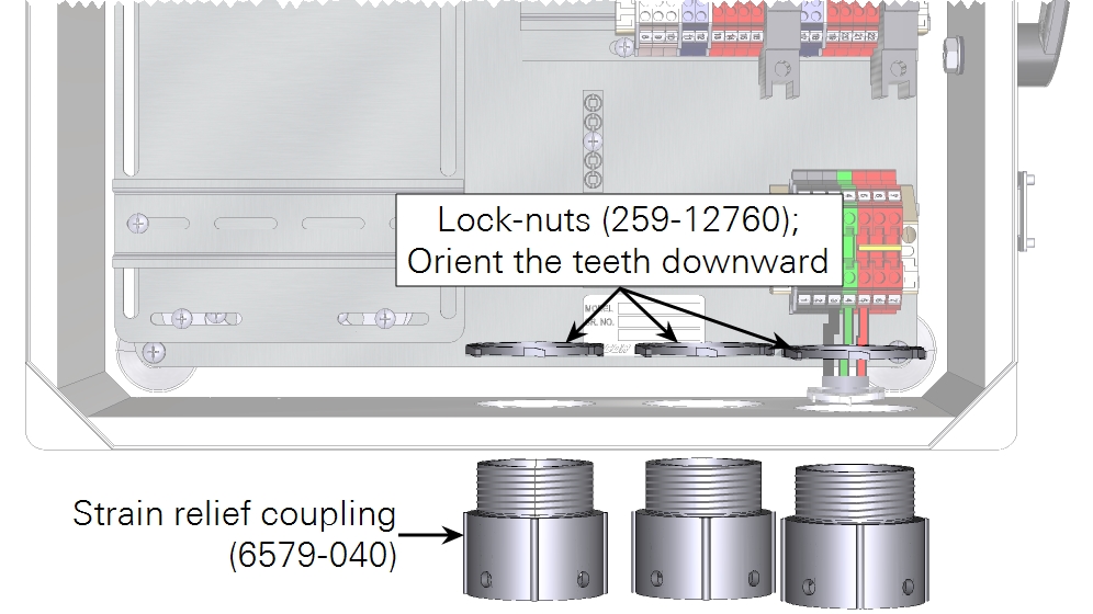
In both the eddy covariance system enclosure (7900-050) and the Biomet Data Acquisition System enclosure (7900-126), install the three strain-relief couplings in the three bottom openings.
In the eddy covariance system enclosure (7900-050), install the Power Distribution Kit (7900-235) on the raised DIN rail. Connect the red wire lead between the top of the breaker and top right red terminal. Install one shorting block to connect all black terminals and another to connect all red terminals.
Installing the SIM card
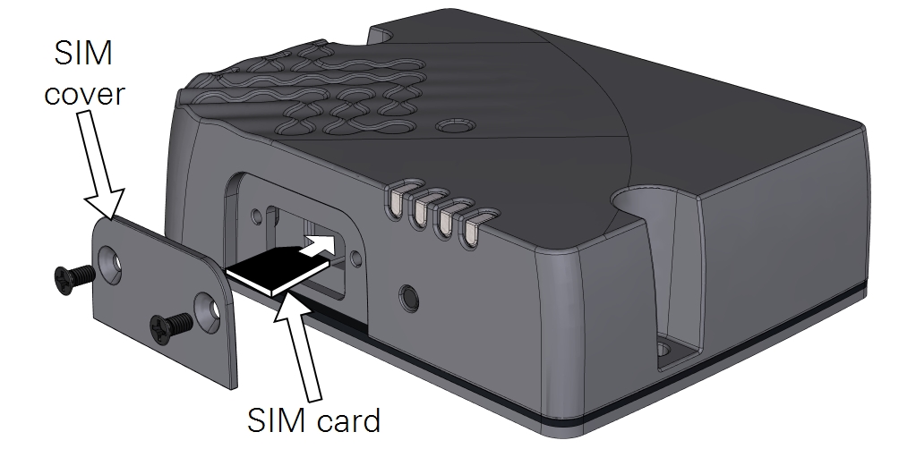
The SIM card installs in the upper slot. The upper slot is the primary slot (SIM 1); do not install the card in the lower slot unless you have both primary and backup cards. Press it in until the card clicks in place, then reinstall the cover.
Attaching the mounting bracket
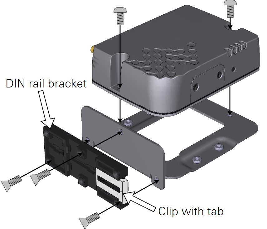
Attach the mounting bracket and connect the DIN rail clip.
Note: Take a picture of the label so you have a record of the information. This will save you the trouble of disassembly later, when you need information that is printed on the label.
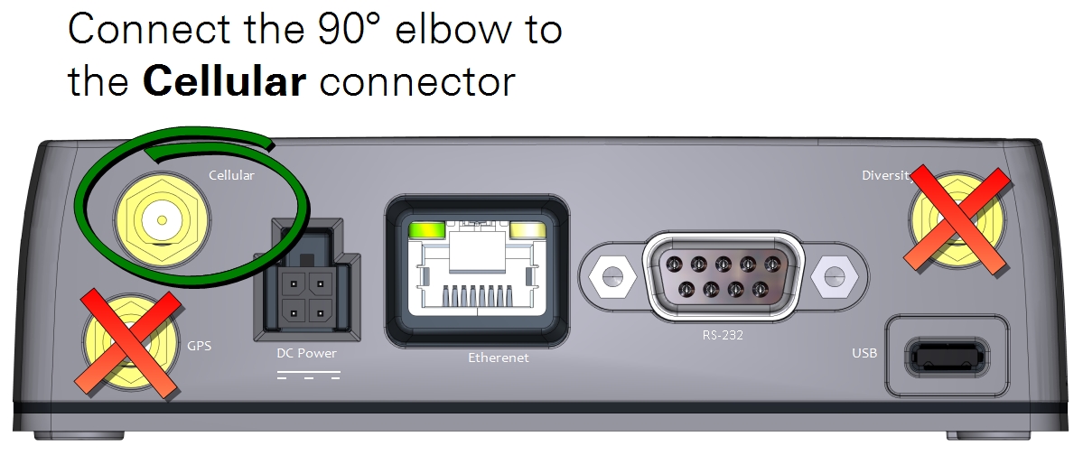
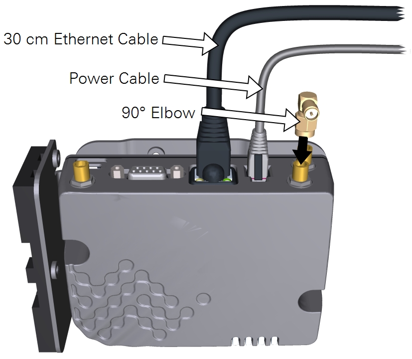
Connecting cables to the RV50X
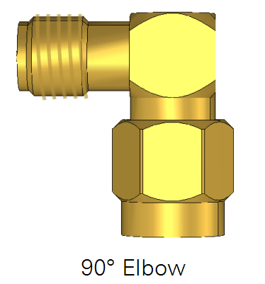
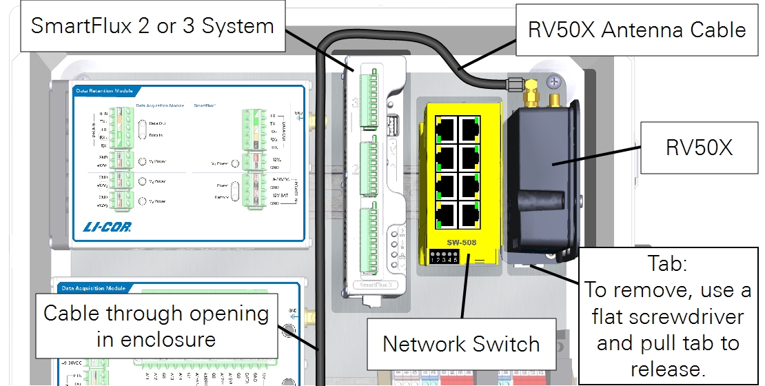
Connect the 30 cm Ethernet cable and power cable to the RV50X. Connect the 90° elbow to the connector labeled Cellular. Connect the antenna cable to the elbow.
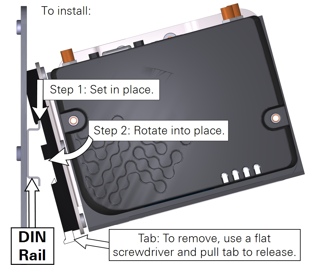
Mounting the RV50X in the enclosure
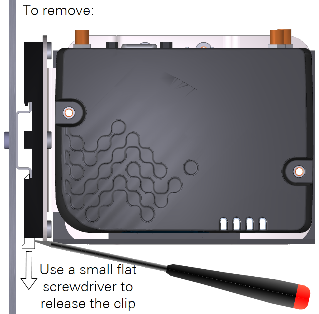
Install the RV50X on the DIN rail. Set the top in place, and then rotate until the lower part clips to the lower rail. To remove it, insert a small flat screwdriver into the slot and release the clip.
Connecting power wires
Note: Do not power on the RV50X yet. Leave the breakers OFF until later in the process (see Power on the system).
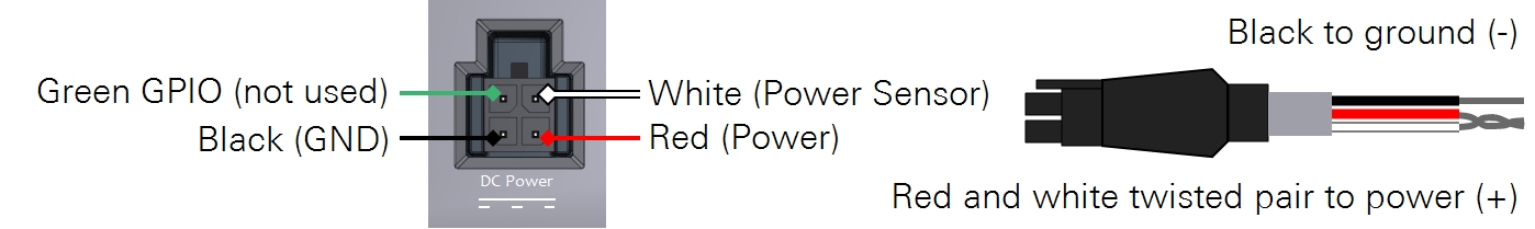
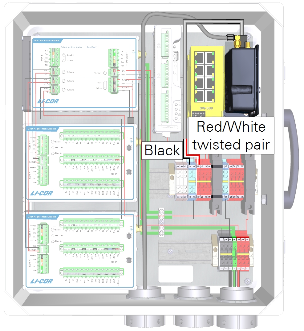
Cut the power cable to a suitable length (30 to 50 cm) and carefully remove about 5 cm (2") of outer insulation. Strip about 1.3 cm (½") of insulation from the black, red, and white wires. Twist the red and white wires together. The green wire is not used. Connect the wire leads to terminals in the enclosure.
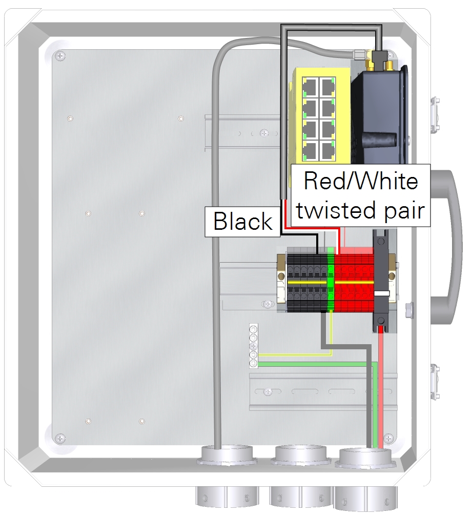
| From | Wire Color | To |
|---|---|---|
| DIN Terminal 11 (top) or Black DIN Terminal | black | RV50X Ground (-) |
| DIN Terminal 13 (top) or Red DIN Terminal | red and white | RV50X Power (+) |
Connecting network cables
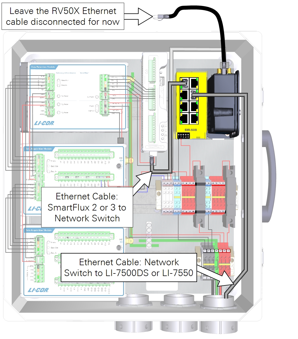
Important: Do not connect the RV50X Ethernet cable to the switch yet. Leave it disconnected until all of the instruments are configured.
Install an Ethernet cable between the LI-7550 or LI-7500DS and the switch; and the SmartFlux System and the switch. Leave the 30-cm Ethernet cable (part number 616-16844) from the RV50X disconnected for now.
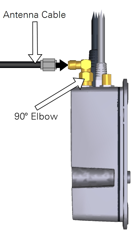
Connecting the antenna
Warning: Maintain at least 20 cm separation distance between the antenna and your body when the RV50X is powered on.
The antenna cable is a slender coaxial cable that attaches to Cellular terminal on the RV50X. The other end connects to the terminal on the bottom of the antenna. Tighten the cable connections securely.
Note: When closing the enclosure, carefully fold over any cables and secure them in the box. Use caution to ensure that the cables are not bent sharply or pinched by the lid.
Installing the antenna in the field
Important: The antenna is a transmitter-receiver that broadcasts electromagnetic radio signals. Some electronic devices, data recorders, and sensors may be susceptible to radio interference from this antenna. Therefore, it is important to position the antenna at a reasonable distance from sensors and data recorders. Never put the antenna in an instrument enclosure, adjacent to instruments on your instrument platform, or pointing toward instruments or cables. Maximize the distance between instruments and the antenna using the provided 4.6 m cable to reduce the chance of radio interference.
Position the antenna so that it has clear reception and does not interfere with the variables you are measuring. Be sure it does not shadow any radiation sensors, obstruct the rain gauge, or obstruct eddies in an eddy covariance system.
- Before you dig!
- Check to ensure that there are no underground gas lines, electrical lines, or unexploded ordnance in the vicinity.
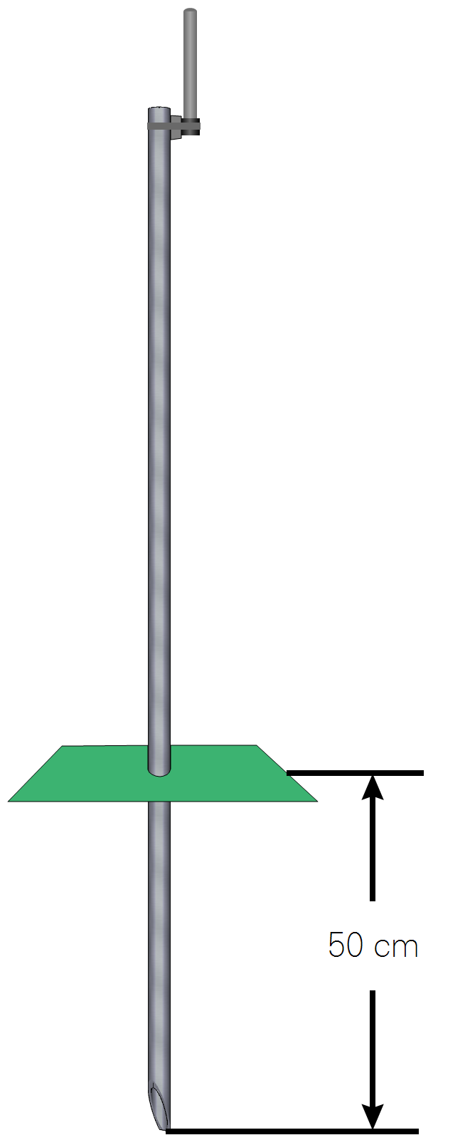
- Drive the antenna mounting post.
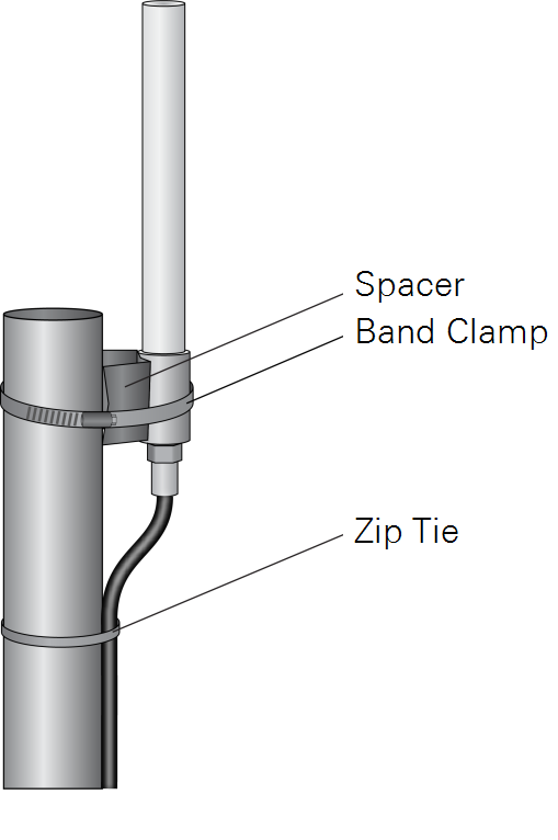
- Drive the post at least 50 cm into the ground and attach the antenna using the included bracket and band clamp. In sandy, muddy, or loose soils additional support may be required to secure the mounting post.
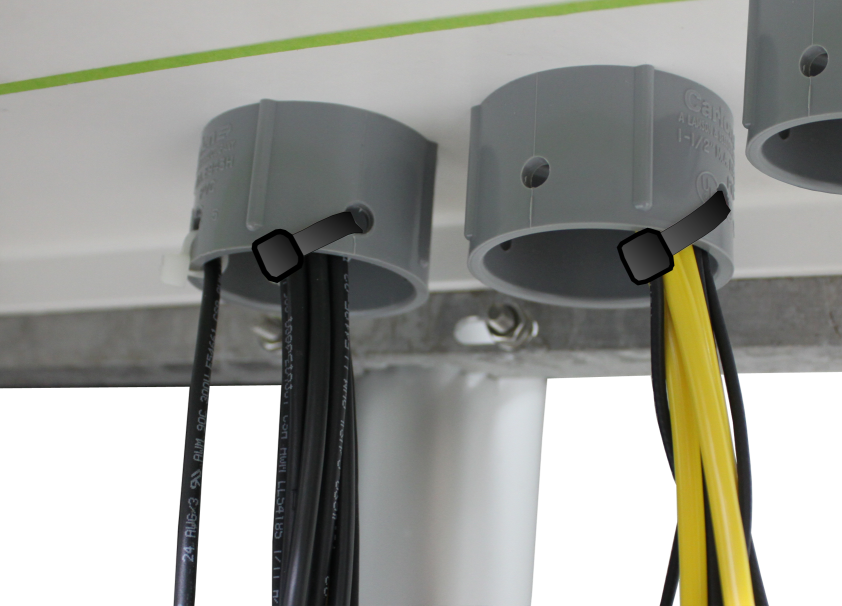
Securing cables
Communication and power cables should be secured so they do not apply strain to connectors and junctions. Secure the cables to the strain-relief plugs as shown.