
Introduction to the communication system
Two models of RV50X are available to support global cellular networks. These are made available from LI-COR as package 7900-715 and 7900-716 (see Table 1‑1). Both packages include all of the hardware required to use the cellular communication system with LI-COR eddy covariance and soil gas flux systems.
| Part Number | Region |
|---|---|
| 7900-715 | North America, South America, Europe, Middle East, Africa |
| 7900-716 | Asia Pacific |
Arranging a data plan
Prior to using the RV50X, arrange a data plan with a wireless service provider that offers cellular coverage at your site. We recommend a public fixed IP address, but see Choosing a SIM and data plan for the RV50X and LI-COR equipment at https://licor.app.boxenterprise.net/s/7xd5z2ko3d7hcwmwz4lpqu5o8tq29aed for more information about the capabilities and limitations of different SIM configurations.
Typically, the service provider will issue a SIM card (mini SIM, 2FF) that must be installed in the modem. They will also provide an IP Address and Access Point Name (APN) that are associated with the SIM card.
What's what
If you have just taken delivery of the communication system, check the packaging list to verify that you received everything ordered. The system will include an RV50X, power cable, data cable, antenna, antenna cable, and mounting hardware.
Overview of the RV50X
An RV50X Quick Start Guide is included in the device. Full documentation is available from Sierra Wireless: (https://source.sierrawireless.com/devices/rv-series/rv50x/).
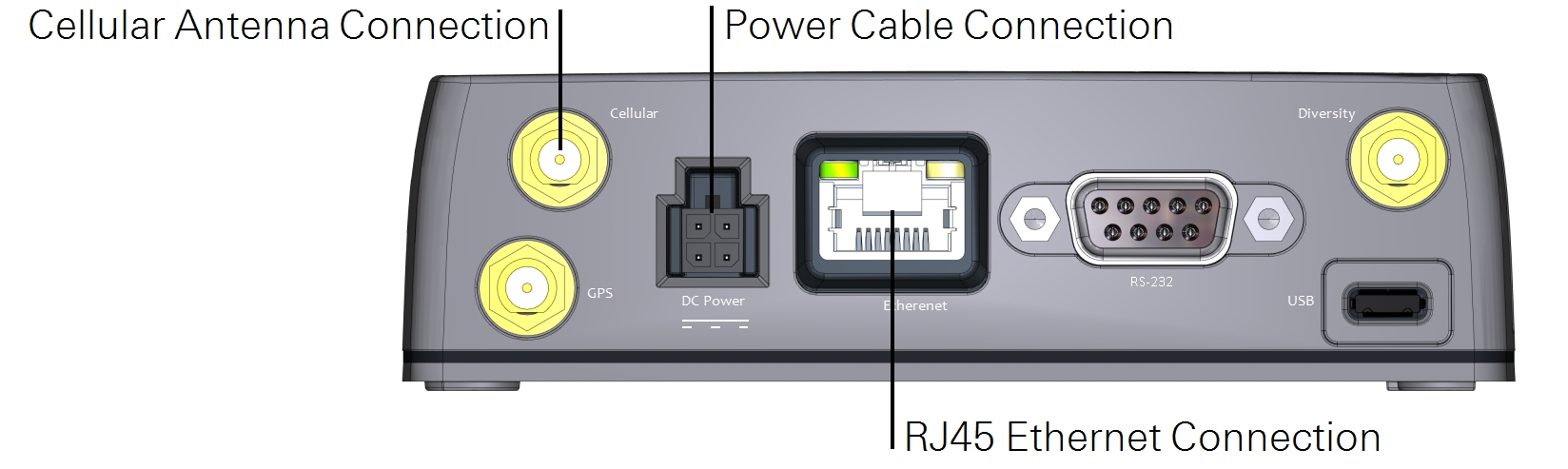
Cable connections
The cable connectors that are used in this application are labeled below.
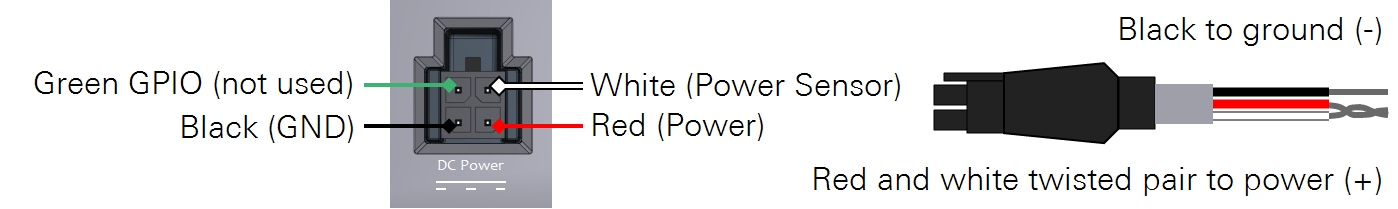
Power connector
In the power cable, the red and white wires must be twisted together and connect to a positive (+) 9 to 36 VDC power supply. The black wire goes to the negative (-). The green wire is not used.
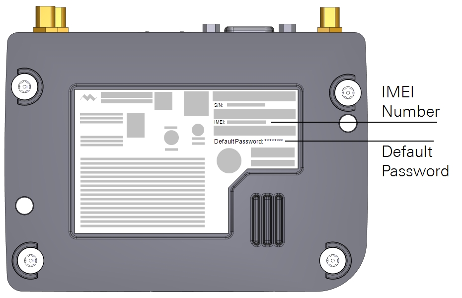
Product labels
You may need certain details about your RV50X, such as the IMEI Number when configuring the data plan. This information is given on the label on the bottom of the RV50X and the packaging box. Devices that support unique passwords have the default password printed on the label. For other devices, the default password is 12345.
Note: Take a picture of the label so you have a record of the information. This will save you the trouble of disassembly later, when you need information that is printed on the label.
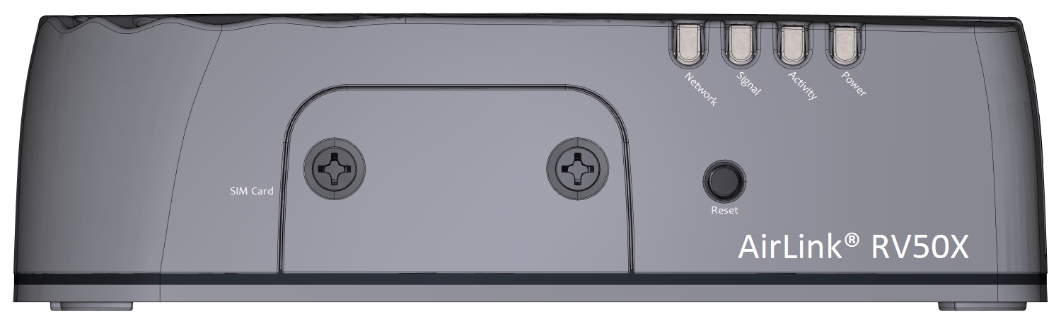
Indicator LEDs
The RV50X indicator panel has four LED lights to indicate the status.
All LEDs
- Green LED chase: Radio module reconfiguration, firmware update, or Network Operator Switching is in progress.
- Amber LED chase: ALEOS software update is in progress.
- Solid Amber: ALEOS software update complete (all LEDs are amber except the Power LED)
- Red LED chase: The RV50X is in Recovery mode.
Network LED
Indicates the status of the network connection.
- Solid Green: Connected to an LTE network. Off when in LED power saving mode.
- Solid Amber: Connected to a 3G network. Off when in LED power saving mode.
- Flashing Green: Connecting to a network.
- Flashing Red: No network available.
- Flashing Red/Amber: Network Operator Switching is enabled. Consult the RV50X documentation for details.
Signal LED
Indicates the cellular signal strength.
- Solid Green: Good signal; equal to about 4 or 5 bars.
- Solid Amber: Fair signal; equal to about 2 or 3 bars.
- Flashing Amber: Poor signal; equal to about 1 bar. Relocate the antenna in an attempt to improve the signal strength.
- Flashing Red: Insufficient signal. Relocate the antenna in an attempt to improve the signal strength.
Activity LED
Indicates data transfer over the cellular network.
- Flashing Green: Data is being transmitted or received over the WAN interface. This behavior only appears if the RV50X is configured to display it.
- Flashing Red: Data is being transmitted or received over the RS-232 Serial connection. This behavior only appears if the RV50X is configured to display it.
- Flashing Amber: Data is being transmitted or received over both the WAN interface and the serial connection.
Power LED
Indicates the input power.
- Off: No power or input voltage is ≥36 VDC or ≤7 VDC.
- Solid Green: Power is present.
- Green with Amber Flash: Power is present and the RV50X has a GPS fix.
- Solid Red: Standby mode.
- Flashing Green: When you press the reset button, flashing green indicates when to release the reset button to reboot the RV50X.
- Flashing Red: When you press the reset button, flashing red indicates when to release the reset button to reset the RV50X to the factory default settings.
- Flashing Amber: When you press the reset button for more than 20 seconds, flashing amber indicates when to release the reset button to enter Recovery mode. Consult the RV50X documentation for details.
Optional accessories
The following accessories are available to support the communication system.
Pre-configured biomet system enclosure
Part Number: 7900-126
The pre-configured enclosure is a large weather resistant box with mounting hardware. It is set up for the LI-COR Biomet Data Acquisition System and other accessories. It includes all of the terminal connections and DIN rails required for a complete eddy covariance system.
Eddy covariance system enclosure
Part Number: 7900-050
A basic enclosure with a minimal set of internal components. Includes a pre-drilled internal back plate, three DIN rails for mounting components, and three strain relief fittings. It is best to pair this with the Power Distribution Kit (7900-235).
Power distribution kit
Part Number: 7900-235
Includes DIN-mountable terminal connections, shorting blocks, and a 10-amp circuit breaker. Provides 11 individual positive and negative power terminals for the system. Installs in the 7900-050 eddy covariance system enclosure.
| Description | Quantity | Part Number |
|---|---|---|
| 10-amp Circuit Breaker; DIN Mountable | 1 | 275-13499 |
| DIN Terminal Cover | 1 | 331-12825 |
| DIN Terminal End Bracket | 2 | 331-12922 |
| Red 4 mm Terminals; DIN Mountable | 6 | 331-13508 |
| Green 4 mm Terminals; DIN Mountable | 1 | 331-13510 |
| Black 4 mm Terminals; DIN Mountable | 6 | 331-13511 |
| 6-position Shorting Box | 2 | 331-13512 |
| 14 AWG Red Wire Lead | 1 | 392-13829 |
| 18 AWG Green/Yellow Ground Wire Lead | 1 | 372-04621 |
35 mm DIN rail
Part Number: 6579-023
Optional DIN rail to mount additional hardware in the eddy covariance system enclosure.