This section introduces the basics of the LAI-2200C, including configuration options, usage considerations, and a guide for making basic measurements. It is recommended that users who are unfamiliar with the LAI-2200C follow the example measurements and become thoroughly acquainted with the practical considerations (in the next two chapters) before attempting real measurements with the LAI-2200C.
Power ON and OFF
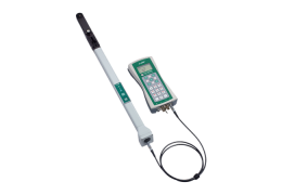
To power on the LAI‑2270C Control Unit (console), press the power button. It is below the left side of the display.
If not attached already, attach an optical sensor (wand) to the X or Y port using the cable (part number 9922-127). The optical sensor should turn on when the control unit is turned on (if the cable is attached), when connected to a powered up control unit, or when the optical sensor power button is pressed.
To turn off the control unit, press the power button. To turn off the optical sensor, press and hold the power button for 2 seconds. The control unit features a user-settable auto-off timer that will shut off the instrument automatically. The auto-off timer can be set for 5-60 minutes. The optical sensor automatically shuts off in 30 minutes if no button is pressed (unless configured for automatic logging or connected to a control unit).
Console Auto-off Timer
To set the auto-off timer on the Control Unit (console), press the MENU button, select Console Setup, then Auto-off Timer. Set the timer as desired and press OK to save the settings.
Monitor Mode Navigation
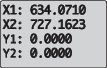
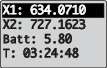
When the LAI-2200C is turned on, Monitor Mode (right) will be displayed. Observe the variables called X1, X2, Y1, and Y2. These are values from rings 1 and 2 from the X and Y sensors. Each row of the Monitor Mode screen can be set to display any one of the values in Table C‑1.
To change variables on the display, press the up or down arrow to select a field. The active field will be highlighted for about 1 second. Press the right or left arrow button to scroll through available variables.
Basic Menu Navigation
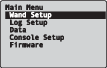
Basic navigation through menus is accomplished with the upper block of 9 keys. When viewing a menu (press the MENU button to view the Main Menu, shown at right), the selected menu level will be highlighted. Press OK or the Right Arrow to select the highlighted menu option, press the Left Arrow key to go back a menu level or toggle field settings, and press EXIT once to return to the Main Menu or twice to return to Monitor Mode.
Setting the Clock
Be sure to set the clock on both the console and optical sensors. The console clock can be set manually (Procedure 1.1 - Setting the Console Clock Manually) or by using the time information from the GPS (Procedure 1.2 - Setting the Console Clock from GPS). Once the clock is set, you can synchronize an optical sensor to the console (Procedure 1.4 - Synchronizing Wand and Console Clock).
Note: If using two optical sensors, the clocks in both must be synchronized in order to match data in time.
Calibration and Match Values
Every wand has two sets of 5-number calibration values: the “permanent” set (accessible via MENU >Wand Setup > Cal Values) and the “working” set (MENU > Wand Setup > Match Values). The match values are always used when the wand is making measurements, while the cal values (which are printed on each wand’s calibration sheet) are there to serve as built-in reset values. For more details on wand calibrations, see Wand Calibrations.
The simplest thing to do with the match values is to reset them to the calibration values (see Procedure 1.5 - Resetting Wand to Factory Calibration), and then leave them alone. With the factory calibration values in place, the ring values of the wand will all read the same when in an isotropic environment, allowing the sky brightness distribution to be measured, which is an important step when doing scattering corrections. The calibration does not ensure that two wands will read the same absolute brightnesses, however, so when two wands are used to obtain data for computing LAI (one wand above the canopy, one below), then an adjustment needs to be made. Further details are in Multiple-Sensor Operation Revisited.