General information
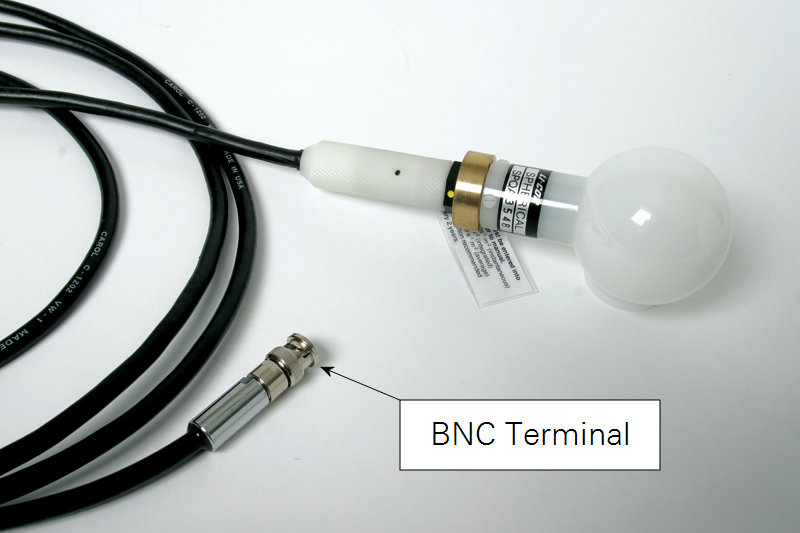
The LI-192SA and LI-193SA underwater quantum sensors have a coaxial cable that terminates with a BNC connector. The 2222UWB Underwater Cables used with LI-COR underwater sensors are terminated with this type of connector, which allows for direct connection to the LI-250A Light Meter or the LI-1500 Light Sensor Logger. Figure 1‑1 shows an LI-193SA sensor with the coaxial connector.
This connector also allows the sensor to be used with older (discontinued) instruments, including the LI-189 Quantum/Radiometer/Photometer, LI-250 Light Meter, the two current channels of the LI-1000 Datalogger, or with older LI-COR integrators.
When a LI-COR Light Meter or data logger is not used, type SA sensors can be used with other millivolt recorders or data loggers by connecting a millivolt output conversion adapter. See Accessories for more information. Note that all LI-COR underwater sensors produce a current signal, not voltage.
Sensor recalibration
Factory recalibration of LI-COR radiation sensors is recommended every two years. Sensors can be returned to LI-COR for this service – please contact our technical support staff for more information.
Getting started
All LI-COR radiation sensors produce a current proportional to the radiation intensity. During factory calibration, sensor output (in microamps) is measured while the sensor is exposed to a standard lamp of known intensity. The sensor output at this intensity has general units of microamps per radiation unit and is called the Calibration Constant (Calconstant). Each sensor has a slightly different output at a given radiation intensity and will therefore have a unique Calconstant.
Relationship between the Calibration Constant and Calibration Multiplier
LI-COR Light Meters and dataloggers measure the current output of the sensor in units of microamps, and convert the measured current to units of radiation. To make this conversion, LI-COR instruments use the sensor Calibration Multiplier. The Calibration Multiplier is the negative reciprocal of the Calconstant.
1‑1

The LI-192 and LI-193 calibration certificates contain calibration multipliers for both in air and in water operation. The in water multiplier includes an immersion effect correction.
To use a type SA sensor with the LI-250A, the calibration multiplier is entered in configuration mode, using the up and down arrow keys to scroll the multiplier value(s).
When using the LI-1400 DataLogger, the calibration multiplier must be entered into the software as described in the Instruction Manual.
When a LI-COR light meter or data logger is not used, your sensor can be used with other millivolt recorders or data loggers by connecting a millivolt adapter. The LI-192SA and LI-193SA underwater sensors require the 2291 Millivolt Adapter, which has a resistance of 1210 Ohms.
The millivolt adapter connects to the BNC connector of the sensor, and the wire leads of the adapter are connected to the data logger. Sensor output (in millivolts) when using the millivolt adapter can be computed using "Ohm's Law" (Voltage = Current × Resistance).
Example: Calculate the millivolt output of an LI-192 Underwater Quantum Sensor which has a calibration constant of 8.0 μA/1000 μmol s-1 m-2. Assume the 2290 millivolt adapter is used with the sensor.
1‑2

The multiplier to use in your data acquisition system is the reciprocal of this result. For example,
1‑3

If the calibration constant for your sensor has been lost or misplaced, it can be obtained from LI-COR by providing the serial number of the sensor.
Important: When using the sensor under water, the "in water" calibration constant should be used to calculate the millivolt output of the sensor. The "in water" sensor calibration includes an immersion effect correction.
Connecting to metering devices from other manufacturers
The use of the millivolt adapter with a recorder or data logger other than LI-COR instruments is often acceptable for radiation levels down to 10% of full sunlight. Below 10%, the recorder must be very sensitive to pick up the small voltage signal. The recorder should have a high impedance input (>1 megaohm, such as potentiometric types), and the range adjustment should be 0 - 10 mV, or a more sensitive range. For low light levels, the sensor should be connected directly to a LI-COR readout device (without using the millivolt adapter).
In LI-COR underwater cables the inner white wire is positive and the black wire is negative. The center pin of the BNC connector has a negative signal. This is done because the trans-impedance amplifier used in LI-COR light meters requires a negative signal.
For data logger or millivolt applications where the millivolt adapter is needed, the positive (green) lead should be connected to the low impedance (common terminal) when plus or minus signal capability is available on the data logger or recorder. This will minimize noise.
If plus or minus capability is not available on the data logger or recorder, the green lead should be connected to the positive input and the blue lead to the negative input. If noise difficulties are encountered, consult LI-COR for special wiring instructions.
Using the 2009S Lowering Frame
It is recommended that the LI-COR 2009S Lowering Frame (or equivalent) be used with the sensor for underwater applications.
Important: Do not use LI-COR 2222UWB Underwater Cable to support the sensor and lowering frame, as damage to the cable can result. An auxiliary cable should be used to support the lowering frame and sensor. In addition, the 2222UWB cable should not be bent sharply near the sensor.
Note: For cable lengths over 75 m (225 ft.), care should be exercised in its use since movement of the cable within the water can cause excessive signal noise.
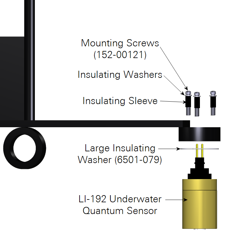
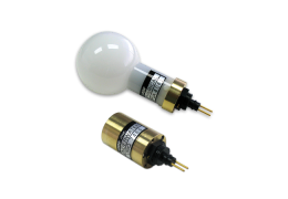
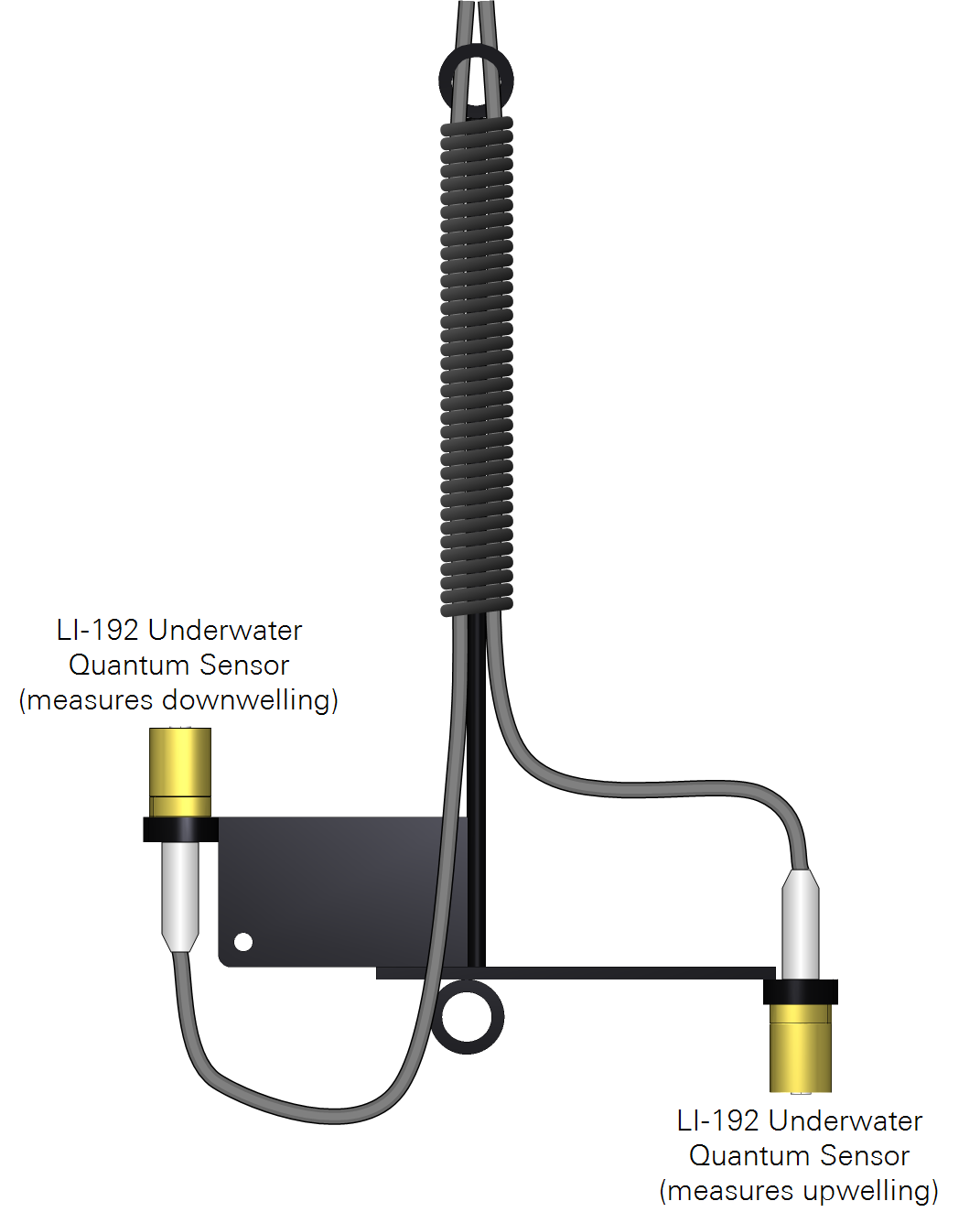
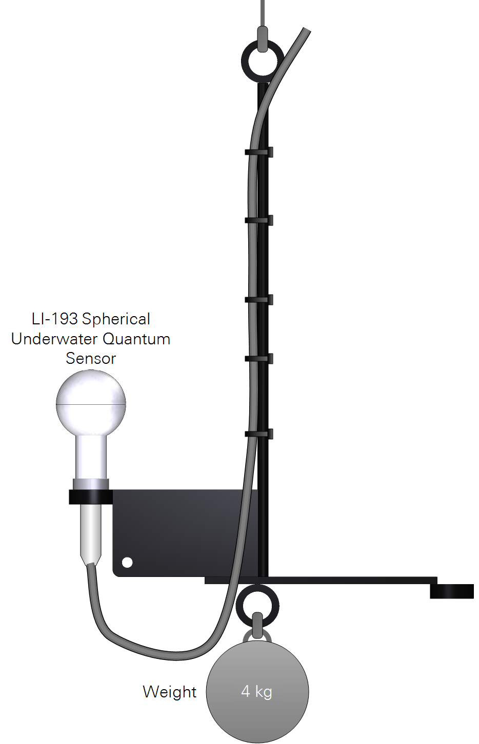
The 2009S Lowering Frame provides for the placement of two cosine sensors, one each for upwelling and downwelling radiation, or a single underwater spherical sensor (Figure 1‑2). Each LI-COR underwater sensor has three 6-32 tapped mounting holes on the underside of the sensor for connection to the mounting ring. Corrosion resistant mounting screws are included with each sensor. A replacement screw and insulating washer kit is available from LI-COR (p/n 9901-220).
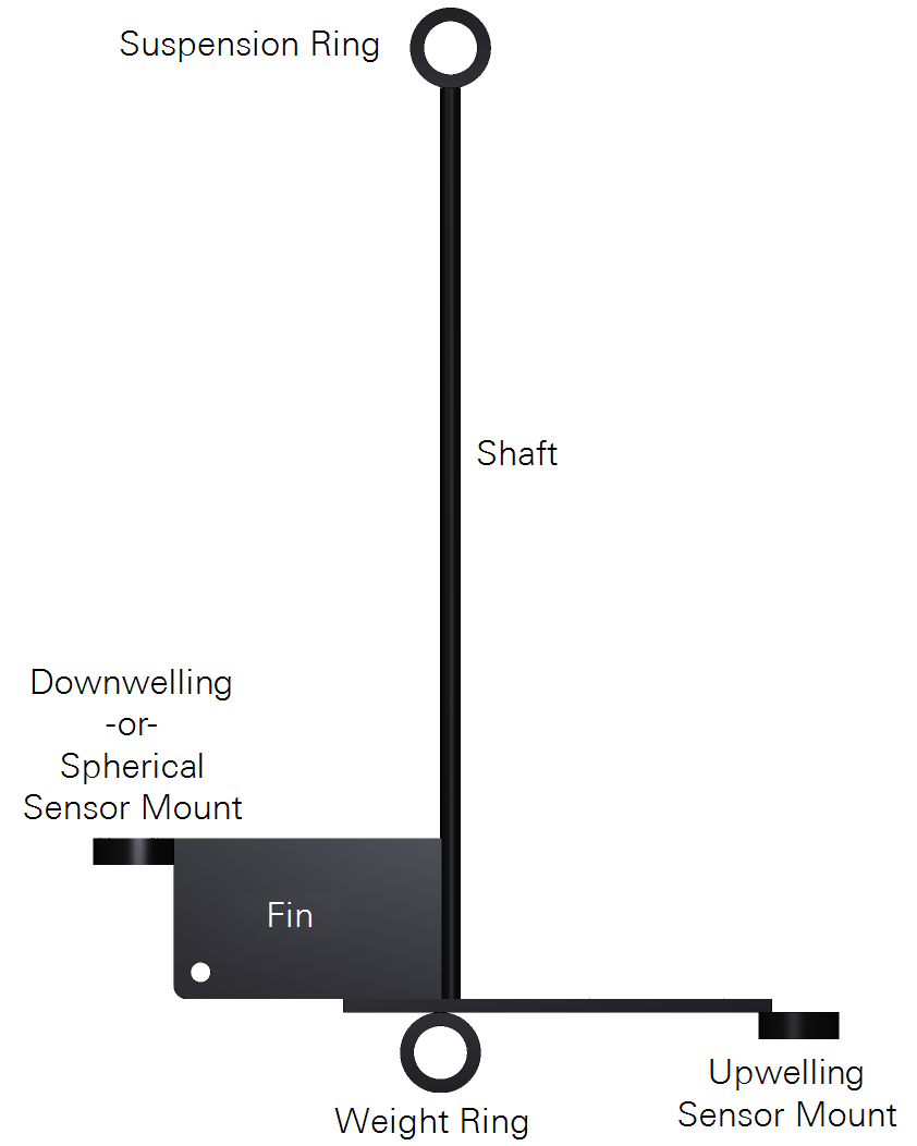
When two sensors are used, the frame is well balanced and will work well in mild currents without twisting the cables. The sensor for downwelling radiation is always attached using the mounting ring on the fin. Likewise, the sensor for upwelling radiation is attached to the opposite mounting ring. Depending on the speed of the current, the frame will tilt a few degrees, but this can be minimized by hanging a compact weight from the weight ring. Moderate weights will often suffice (4 kg). Weights over 25 kg should be avoided.
The use of a single cosine sensor will require a small weight (0.2 kg) attached at the empty mounting ring or a moderate weight from the weight ring, or possibly both, depending upon the speed of the current. The underwater cable(s) should be attached to the frame such that approximately 25 cm of cable forms a smooth arc to the underwater sensor connector and is restrained from being flexed or supporting any weight.
The LI-COR underwater cable is not recommended as a support cable, although it can be used as a lowering cable providing it is properly attached and the attached weights do not exceed 5 kg. The cable(s) must be attached as described above. Additionally, the cable must be securely attached to the shaft of the lowering frame at multiple points so that the cable does not slip and put strain on the sensor connector. However, the cable cannot be clamped so tightly as to damage it. Possible methods to use are numerous nylon cable clamps along the length of the shaft, or a tight wrap of light cord around the shaft and cables, starting at the suspension ring and extending downward at least 25 cm.
For long-term immersion or use in heavily ionic water, it may be necessary to provide electrical insulation between the underwater sensor(s) and the lowering frame to prevent galvanic corrosion. This is accomplished by slipping an insulating flat washer over the mounting screws down to the heads, followed by a 1/2" (13 mm) length of thin tubing over the screw threads. This tubing insulates the screws from the mounting ring.
Next, place a large flat insulating washer between the sensor and the mounting ring (with three holes for the screws). Use the "insulated" screws to attach the sensor in place. In this way, neither the screws nor sensor have electrical contact with the frame.