This section introduces the LI-3000C Leaf Area Meter.
System description
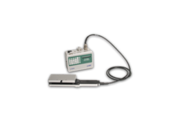
The LI-COR Model LI-3000C Portable Area Meter uses an electronic method of rectangular approximation to measure leaf area on intact plants of many species. The LI-3000C has two components, the Scanning Head and the Readout Console. Area data are logged by the Readout Console as the Scanning Head is passed over the leaf.
The LI-3000C has the following features:
- Displays leaf length, average width, and maximum width in addition to area and accumulated area.
- Readings can be summed in a secondary summing register at the user's command. The previous reading added to the register can be subtracted from it.
- Readings can be stored in the console, or output to a computer via Windows® interface software (RS-232 or USB).
- The console can be used with the LI-3050C Transparent Belt Conveyer Accessory.
- Real-time monitoring and data collection is provided with Windows® interface software.
- A rechargeable lead acid battery provides power for portable operation. The battery life is approximately 12 hours.
The LI-3000C is designed for field use; however, care should be taken during operation and storage. The instrument is not waterproof, and care should be taken to avoid exposure to excessive moisture. The 3000A-02 Carrying Case is recommended.
Optional accessories for the LI-3000C include the 3000A-02 Carrying Case and the LI-3050C Transparent Belt Conveyer Accessory.
What’s what
If you have just taken delivery of your LI-3000C, check the packing list to verify that you received everything ordered, including the following items:
Scanning head
The scanning head is calibrated to the readout console at the factory. The calibration routine computes how much current each of the 128 LEDs requires in order to achieve a uniform brightness. These calibration values are retained in the memory of the console. Only scanning heads with serial numbers above #196 can be used with the LI-3000C.
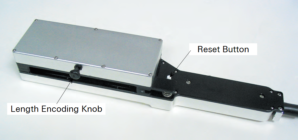
The scanning head is opened by pressing the thumb lever at the top of the handle (Figure 1‑1). The open scanning head is placed over the leaf, after which the length encoding cord is drawn out and held in a fixed position. The scanning head reset (white) button is pressed once to clear the X register, the scanning head is closed, and the head is moved over the leaf while the length encoding cord is held stationary. After the scanning head has passed over the leaf, the length encoding cord is allowed to rewind into the scanning head.
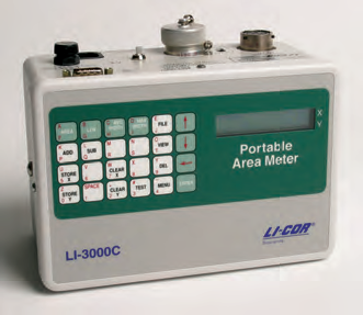
Readout console
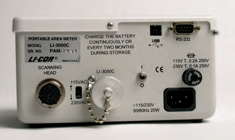
Area data are logged by the readout console as the scanning head is passed over a leaf. The console can also be used with the LI-3050C Transparent Belt Conveyer Accessory. The readout console back panel contains the connections for the scanning head and the LI-3050C, as well as for AC power and RS-232 and USB data output (Figure 1‑2).
Standard RS-232 cable
Part Number: 9975-016
The Standard RS-232 Cable is a DTE to DTE cable with 9-pin connectors on both ends. This cable mates with the RS-232 connector on the readout console back panel; the other end should be used to connect to your computer’s 9-pin serial port. If you want to interface to a computer with a 25-pin serial port, then a 9-pin to 25-pin adapter must be used.
USB cable
Part Number: 392-06652
The 6’ USB cable is terminated with an A and a B type connector. The (smaller) B type connector plugs into the back of the readout console; the larger A type connector is used to connect to your computer.
Spare parts kit
Part Number: 9910-309
This box contains replacement parts for your LI-3000C. As you become familiar with the instrument you will learn which items to keep close at hand and which items can be stored away. The spares kit contains the RS-232 and USB cables, spare fuses, and the waist strap assembly, among other items.
Theory of operation
The method by which the LI-3000C measures area is best understood by examining the technique for manual area measurement. Manual area measurement requires tracing the outline of the sample on graph paper and methodically counting the squares where the sample covers fifty percent or more of the area of an individual grid cell.
The 50% criterion for the acceptance or rejection of grid cells is necessary to maintain linearity in the measured area. In other words, if the grid cells with fifty percent or more area covered were not counted, the result would be inconsistent data on repeated measurements. Similarly, if a sample were cut into pieces and the individual pieces summed, the results would likely not equal the measurement of the whole sample (unless the 50% criterion was used).
The width of the sample at a given point is determined by the number of grid cells covered across a row. The number of grid cells covered in a column determines the length. The resolution of this measurement technique is a function of the area represented by each grid cell.
The LI-3000C Portable Area Meter uses electronic methods to simulate a grid pattern on the leaf. The scanning head uses a row of 128 narrow band, red, light-emitting diodes (LEDs), spaced on 1 mm centers, to examine 128 grid cells across the width of the leaf. The LEDs are sequentially pulsed (only one LED is lit at a time) to examine a particular grid cell in the row. The LEDs are located along a line 0.62 cm (0.25 in.) from the edge of the upper section of the scanning head.
The base of the scanning head contains a lens-photodiode system which responds only to the collimated, pulsed LED light. This design makes the measurements insensitive to other light sources. These narrow-band red LEDs and associated digital circuitry provide measurements which are unaffected by leaf transmission properties.
After each grid cell in the row is scanned, it is necessary to advance to the next row. Electronically, this is accomplished by pulling the length encoding cord. After each 1 mm of cord travel, a new scan is initiated in which each of the 128 LEDs are sequentially pulsed. The scanning process begins only when the length encoding cord is pulled.
Since 1 mm of cord travel is equivalent to the side of a grid cell, it is apparent that the length encoding cord must be pulled perpendicular to the row of 128 LEDs.
When the LED light is blocked by a sample, the unit area (1 mm2) is accumulated on the display. For example, if a 20 ×100 mm sample is being measured, 20 LEDs will be masked for 100 scans resulting in a display of 20.00 cm2.
Any LED that is diminished by 50% or more is accumulated as 1 mm2 of area. This criteria is determined by Menu parameters ‘3000 Threshold’ when using the scanning head in normal operating mode, or ‘3050 Threshold’ when using the LI-3050C Belt Conveyer.
The scanning head accurately measures irregularly shaped leaves or leaves with holes from insect damage. As a hole in the leaf passes through the scanning head, the photodiodes sense LED light, and that LED location does not contribute to the area accumulating on the display until the LEDs are once again masked when the hole has passed.
The important aspect of this electronic measurement technique is that it requires that the light emitted from each of the 128 LEDs be uniform in intensity so that the 50% acceptance/rejection threshold is consistent for each grid cell. This is accomplished by the autocalibration software during the calibration process.
Instrument calibration
The scanning head is calibrated to the readout console at the factory using the LI-3000C's built-in calibration routine (see Calibrate). If a different scanning head is to be used, the calibration routine must be performed to calibrate the head to the console. The calibration routine computes how much current each of the 128 LEDs requires in order to achieve a uniform brightness. These calibration values are retained as a table in the memory of the console.